INSTRUCTION MANUAL DCHT Digital Transmitter DCHT, DCHT/E01 Quick Start Steps 1) Install good batteries and turn power on (see pages 5 and 7). 2) Set compatibility mode to match the receiver (see page 11). 3) Connect signal source, select input type and adjust input gain for optimum modulation level (see page 10). 4) Set or sync frequency to match receiver (see page 11, 12). Also see receiver manual for scanning procedure. 5) Set encryption key type and sync with receiver (see page 13).
DCHT, DCHT/E01 Table of Contents Quick Start Steps................................................................. 1 Introduction............................................................................ 3 General Technical Description ............................................ 3 DSP-controlled Input Limiter................................................ 3 Encryption............................................................................ 3 Features and Functions...................................
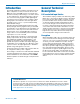
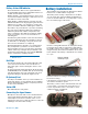
Digital Transmitter Introduction The DCHT, DCHT/E01 transmitter is designed to work with a companion receiver (such as the Lectrosonics M2R, part of the Duet IEM system) as an audio relay between an audio production bag or cart and a camera or other audio device. The 6-pin input jack accepts two mic or line level analog signals or AES digital signals from external sources with a variety of adapter cables.
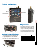
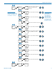
DCHT, DCHT/E01 Features and Functions Status Ready LED Battery status LED Menu navigation Enter menu/Select item USB Port Return to previous screen Programmable function switch Audio input jack Power Bi-directional IR port Whip Antennas Modulation indicators* Antenna port Optional Battery Eliminator The transmitter can be powered by external DC using the optional LTBATELIM power supply adapter. The battery door is replaced by the adapter with a simple procedure.
Digital Transmitter Battery Status LED Indicator The Power/Function LED on the top panel will mirror the keypad LED unless the programmable switch is set to Mute, and the switch is turned on. Alkaline, lithium or rechargeable batteries can be used to power the transmitter. The type of batteries in use are selectable in a menu on the LCD. When alkaline or lithium batteries are being used, the LED labeled BATT on the keypad glows green when the batteries are good.
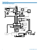
DCHT, DCHT/E01 DCHT, DCHT/E01 Block Diagram Input Jack 1 2 3 4 5 6 CHANNEL 1 CHANNEL 2 (analog/digital selectable) Servo Bias Supply Input Preamp Bias Voltage 0, 2 or 3.6V HI/Lo Pass Filter Audio Gain Adj Shunt Limiter Servo Bias Supply A-D Converter HI/Lo Pass Filter Input Preamp I2S Rate Converter Bias Voltage 0, 2 or 3.
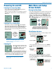
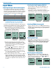
Digital Transmitter Powering On and Off Powering On in Operating Mode Press and hold the Power Button progress bar on the LCD finishes. briefly until the When you release the button, the unit will be operational with the RF output turned on and the Main Window displayed. Hold for Rf On DCHT MUTE 470.100 -40 -20 +0 Powering On in Standby Mode A brief press of the power button , and releasing it before the progress bar finishes, will turn the unit on with the RF output turned off.
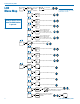
DCHT, DCHT/E01 LCD Menu Map Input... SEL BACK Gain 1 20 2 22 Rolloff Settings will be stored when the BACK button is pressed. StMode InType SEL button to select channel (gain value highlighted) SEL BACK SEL BACK SEL BACK Xmit... InpCfg1 SEL BACK InpCfg2 SEL BACK Freq. SEL BACK 470.675 Txpower Compat Rf On? M2R... SEL BACK GetFrq SendFrq SendAll Name... Flex...
Digital Transmitter Key... SEL BACK NOTE: The key menu selections only show when DCH(X) compatibility mode (encryption) is selected. KeyType MakeKey SEL BACK SEL BACK WipeKey SendKey SEL BACK SEL BACK Setup...
DCHT, DCHT/E01 Input Menu Selecting the Low Frequency Roll-off Adjusting the Input Gain for Analog Inputs For analog gain adjustment, two multi-color LEDs on the top panel, one for each channel, provide a visual indication of the audio signal level entering the transmitter. The LEDs will glow either red or green to indicate modulation levels as shown in the following table.
Digital Transmitter TYPE DESC, BIAS, IMPEDANCE, POLARITY Line In Line level signals up to +24 dBu Dynamic Low-Z dynamic microphones PSA Point Source Audio lav microphones DPA DPA lavaliere; 4V, Mid-Z, (+) B6 Countryman B6; 2V, Low-Z, (+) COS-11 Sanken COS-11; 4V, Low-Z, (–) MKE 2* Sennheiser MKE 2; 4V, Low-Z, (+) M152* Lectrosonics M152; 4V, Low-Z, (+) Oth Lav* Other lavaliere; 4V, Low-Z, (+) Custom Manually configurable microphone level * Separate listings for these microphones are i
DCHT, DCHT/E01 Selecting M2R Receiver Functions The M2R Receiver includes a FlexList™ mode where up to 16 mixes can be accessed by name. This feature enables a user to quickly find and listen to any of the performer’s mixes on the stage. The mix includes the name, frequency, mixer settings and limiter settings. The mix is easily shared via the M2R IR port, added to the list of 16 mixes and stored until cleared by the user.
Digital Transmitter Key Menu SendKey Encryption Key Management KeyType The DCHT has four options for encryption keys: • Universal: This is the most convenient encryption option available. All encryption-capable Lectrosonics transmitters and receivers contain the Universal Key. The key does not have to be generated by the DCHT. Simply set a Lectrosonics encryptioncapable receiver and the DCHT to Universal, and the encryption is in place.
DCHT, DCHT/E01 Enable/Disable Remote Control Function The “dweedle tone” remote control is turned on or off with the Remote menu, setting the transmitter to react to tones received (Enable) or to Ignore the tones. Setup... AutoOn? ProgSw Remote Enable Ignore Options to turn the control panel LEDs on or off. The voltage drop over the life of different batteries varies by type and brand. Be sure to set the correct battery type for accurate indications and warnings.
Digital Transmitter Firmware Update Instructions Firmware updates are made with a file downloaded from the web site and the DCHT, DCHT/E01 connected via USB. The USB port on the transmitter requires a micro-B male plug on the connecting cable. The other end of the cable would normally be a USB A-Type male connector to fit the most common type of USB jack used on computers.
DCHT, DCHT/E01 Input Connections The 6-pin input jack accommodates two discrete channels at microphone or line levels. The input connections are configured as follows: ANALOG DIGITAL Pin 1 CH 1 Shield/Gnd AES GND Pin 2 CH 1 Mic level Pin 3 CH 1 Line level Pin 4 CH 2 Mic level Pin 5 CH 2 Shield/Gnd Pin 6 CH 2 Line level NOTICE: Any microphone wired using pin 2 for electret bias will NOT work with the DCHT, DCHT/E01 and MCTA6TA5M2 adapter.
Digital Transmitter Microphone Cable Termination for Non-Lectrosonics Microphones TA6F Connector Assembly Mic Cable Stripping Instructions 5 6 1 2 4 3 0.15" VIEWED FROM OUTSIDE 0.3" Crimping to Shield and Insulation Strip and position the cable so that the clamp can be crimped to contact both the mic cable shield and the insulation. The shield contact reduces noise with some microphones and the insulation clamp increases ruggedness.
DCHT, DCHT/E01 DCHTRemote By New Endian LLC DCHTRemote is a mobile application for iOS operating systems to remotely control the Lectrosonics DCHT Transmitter. The app remotely changes settings on the transmitter through the use of encoded audio tones, which when received by the attached microphone, will alter the configured setting. The app is available for download and sells for about $25 on the Apple App Store.
Digital Transmitter For body worn operation, this transmitter model has been tested and meets the FCC RF exposure guidelines when used with the Lectrosonics accessories supplied or designated for this product. Use of other accessories may not ensure compliance with FCC RF exposure guidelines. Contact Lectrosonics if you have any questions or need more information about RF exposure using this product.. This device complies with FCC radiation exposure limits as set forth for an uncontrolled environment.
DCHT, DCHT/E01 Accessories 26895: Wire belt clip MCTA6PT: General purpose cable with TA6FLX 6-pin female on one end and stripped and tinned wires on the other end with two separate cables. Wired for connection to microphone level signals. 18 inch length. BCSLEBN: Spring-loaded belt clip MCTA6TA3F2: Line level signals from two TA3-M outputs. 18 inch length. LTBATELIM: Replaces the batteries for powering the DCHT, DCHT/E01 from external DC, 5 to 25 volts.
Digital Transmitter Troubleshooting Symptom: Possible Cause: Transmitter Battery LED off when Power Switch “ON” 1. Batteries are inserted incorrectly. 2. Batteries are low or dead. No Transmitter Modulation LEDs when Signal Should be Present 1. 2. 3. 4. Receiver Indicates RF But No Audio 1. 2. Receiver RF Indicator Off 1. 2. 3. 4. 5. No Sound (Or Low Sound Level), Receiver Indicates Proper Audio Modulation Gain control turned all the way down.
DCHT, DCHT/E01 Service and Repair If your system malfunctions, you should attempt to correct or isolate the trouble before concluding that the equipment needs repair. Make sure you have followed the setup procedure and operating instructions. Check the interconnecting cables and then go through the Troubleshooting section in this manual. We strongly recommend that you do not try to repair the equipment yourself and do not have the local repair shop attempt anything other than the simplest repair.
Digital Transmitter Rio Rancho, NM 23
LIMITED ONE YEAR WARRANTY The equipment is warranted for one year from date of purchase against defects in materials or workmanship provided it was purchased from an authorized dealer. This warranty does not cover equipment which has been abused or damaged by careless handling or shipping. This warranty does not apply to used or demonstrator equipment. Should any defect develop, Lectrosonics, Inc. will, at our option, repair or replace any defective parts without charge for either parts or labor.