
User's Manual
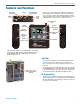

DBu, DBu/E01
LECTROSONICS, INC.
8
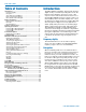
Main Menu and Setup
Screen Details
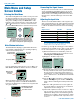
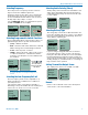
Entering the Main Menu
The LCD and keypad interface makes it easy to browse
the menus and make the selections for the setup you
need. When the unit is powered up in either the oper-
ating or the standby mode, press MENU/SEL on the
keypad to enter a menu structure on the LCD. Use the
and arrow buttons to select the menu item. Then
press the MENU/SEL button to enter the setup screen.
-40
-20
0
Gain
25
The prompt in the upper right corner may
display one or both arrows, depending upon
what adjustment can be made. If the changes
are locked, a small padlock symbol will appear.
Gain
Freq.
ProgSw
Rolloff
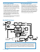
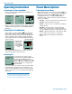
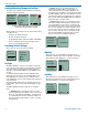
Main Window Indicators
The Main Window displays programmable switch func-
tion, Standby or Operating mode, operating frequency,
audio level and battery status.
470.100
-40
-20
+0
DBu
MUTE
Frequency (MHz)
Operating
mode
Battery status
Audio level
Programmable
Switch Function
If the programmable switch function is set for Mute, the
Main Window will indicate that the function is enabled.
470.100
-40
-20
+0
DBu
MUTE
Mute function
enabled but
not active
When the switch is turned on, the mute icon appear-
ance will change and the word MUTE will blink at the
bottom of the display. The -10 LED on the top panel will
also glow solid red.
470.100
DBu
MUTE
<–MUTE–>
Main Window will blink
the word MUTE when
the audio is muted
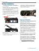
Connecting the Signal Source
Microphones, line level audio sources and instruments
can be used with the transmitter. Refer to the section
entitled Input Jack Wiring for Different Sources for
details on the correct wiring for line level sources and
microphones to take full advantage of the Servo Bias
circuitry.
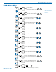
Adjusting the Input Gain
The two bicolor Modulation LEDs on the top panel pro-
vide a visual indication of the audio signal level entering
the transmitter. The LEDs will glow either red or green
to indicate modulation levels as shown in the following
table.
Signal Level -20 LED -10 LED
Less than -20 dB Off Off
-20 dB to -10 dB Green Off
-10 dB to +0 dB
Green Green
+0 dB to +10 dB
Red Green
Greater than +10 dB Red Red
NOTE: Full modulation is achieved at 0 dB, when
the “-20” LED first turns red. The limiter can cleanly
handle peaks up to 30 dB above this point.
It is best to go through the following procedure with the
transmitter in the standby mode so that no audio will en-
ter the sound system or recorder during adjustment.
1) With fresh batteries in the transmitter, power the
unit on in the standby mode (see previous section
Powering On in Standby Mode).
2) Navigate to the Gain setup screen.
Gain
Freq.
ProgSw
Rolloff
-40
-20
0
Gain
25
3) Prepare the signal source. Position a microphone
the way it will be used in actual operation and have
the user speak or sing at the loudest level that oc-
cur during use, or set the output level of the instru-
ment or audio device to the maximum level that will
be used.
4) Use the and arrow buttons to adjust the gain
until the –10 dB glows green and the –20 dB LED
starts to flicker red during the loudest peaks in the
audio.
5) Once the audio gain has been set, the signal can
be sent through the sound system for overall level
adjustments, monitor settings, etc.
6) If the audio output level of the receiver is too high or
low, use only the controls on the receiver to make
adjustments. Always leave the transmitter gain ad-
justment set according to these instructions, and do
not change it to adjust the audio output level of the
receiver.