
User's Manual
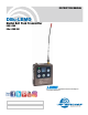

DBu-LEMO, DBu-LEMO/E01
LECTROSONICS, INC.
2
Introduction
The DBu-LEMO transmitter employs high efficiency
digital circuitry for extended operating time on two AA
batteries. The transmitter can tune in coarse or fine
steps across the UHF television band from 470.100 to
607.950 MHz (E01: 470.100 - 614.375 MHz), with a
selectable output power of 10, 25 or 50 mW. The pure
digital architecture enables AES 256-CTR encryption
for high level security applications.
Studio quality audio performance is assured by high
quality components in the preamp, wide range input
gain adjustment and DSP-controlled limiting. Input
connections and settings are included for any lavaliere
microphone, dynamic microphones and line level inputs.
Input gain is adjustable over a 44 dB range in 1 dB
steps to allow an exact match to the input signal level,
to maximize the dynamic range and signal to noise
ratio.
Frequency Agility
The transmitter tunes across the entire frequency
range, from 470.100 MHz to 607.950 MHz (E01:
470.100 - 614.375).
Encryption
When transmitting audio, there are situations where pri-
vacy is essential, such as during professional sporting
events, in court rooms or private meetings. For instanc-
es where your audio transmission needs to be kept
secure, without sacrificing audio quality, Lectrosonics
introduces Encryption Keys. Truly entropic encryption
keys are first created by a Lectrosonics receiver, such
as the DSQD Receiver. The key is then synced with the
DBu-LEMO via the IR port. The audio will be encrypted
and can only be listened to if both DBu-LEMO and re-
ceiver have the matching encryption key. If you are try-
ing to transmit an audio signal and keys do not match,
all that will be heard is silence or white noise.
DSP-controlled Input Limiter
The transmitter employs a digitally-controlled analog
audio limiter prior to the analog-to-digital converter.
The limiter has a range greater than 30 dB for excellent
overload protection. A dual release envelope makes the
limiter acoustically transparent while maintaining low
distortion. It can be thought of as two limiters in series,
connected as a fast attack and release limiter followed
by a slow attack and release limiter. The limiter recovers
quickly from brief transients, so that its action is hidden
from the listener, but recovers slowly from sustained
high levels to keep audio distortion low and preserve
short term dynamic changes in the audio.
Table of Contents
Introduction ........................................................................... 2
Frequency Agility................................................................. 2
Encryption ........................................................................... 2
DSP-controlled Input Limiter ............................................... 2
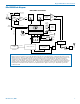
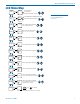
DBu-LEMO Block Diagram ................................................. 3
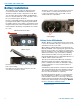
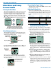
Battery Installation ............................................................... 4
Battery Status LED Indicator .............................................. 4
Belt Clips ............................................................................. 5
IR (infrared) Port ................................................................. 5
Audio Input .......................................................................... 5
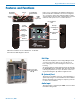
Features and Functions ....................................................... 5
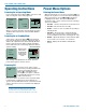
Operating Instructions ......................................................... 6
Powering On in Operating Mode ......................................... 6
Powering On in Standby Mode ........................................... 6
Powering Off ....................................................................... 6
Power Menu Options ............................................................ 6
Entering the Power Menu .................................................... 6
LCD Menu Map ...................................................................... 7
Main Menu and Setup Screen Details ................................. 8
Entering the Main Menu ...................................................... 8
Main Window Indicators ..................................................... 8
Connecting the Signal Source ............................................ 8
Adjusting the Input Gain ...................................................... 8
Selecting Frequency ........................................................... 9
Selecting Programmable Switch Functions......................... 9
Selecting the Low Frequency Roll-off ................................. 9
Selecting Audio Polarity (Phase) ......................................... 9
Selecting Battery Type ........................................................ 9
Setting Transmitter Output Power ....................................... 9
Remote Function ................................................................. 9
Locking/Unlocking Changes to Settings.............................. 10
Restoring Default Settings .................................................. 10
KeyType .............................................................................. 10
WipeKey .............................................................................. 10
SendKey .............................................................................. 10
LectroRM ............................................................................... 11
Whip Antennas .................................................................... 12
Encryption Key and Settings Transfer ............................... 12
Microphone Wiring ............................................................... 13
Line Input Wiring and Use ................................................... 13
Accessories .......................................................................... 13
Wireless Designer Software ............................................... 14
Firmware Update Instructions ............................................. 14
Specifications ....................................................................... 15
Troubleshooting .................................................................... 16
Service and Repair ............................................................... 17
Returning Units for Repair .................................................. 17