
Instruction Manual

DBSM-A1B1, DBSM/E01-A1B1, DBSMD-A1B1, DBSMD/E01-A1B1
LECTROSONICS, INC.
2
Introduction
The design of the DBSM/DBSMD transmitter delivers
the advanced technology and features of Digital Hy-
brid Wireless
®
in a Lectrosonics belt-pack transmitter
at a modest cost. Digital Hybrid Wireless
®
combines a
24-bit digital audio chain with an analog FM radio link
to eliminate a compandor and its artifacts, yet preserve
the extended operating range and noise rejection of the
finest analog wireless systems.
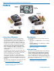
The housing is a rugged, machined aluminum pack-
age with a standard Lectrosonics 5-pin input jack for
use with electret lavaliere mics, dynamic mics, musical
instrument pickups and line level signals. The LEDs
on the keypad allow quick and accurate level settings
without having to view the receiver. The unit is powered
by AA batteries, and the antenna port uses a standard
50 ohm SMA connector.
Switching power supplies provide constant voltages to
the transmitter circuits from the beginning to the end of
battery life, with output power remaining constant over
the life of the battery. The input amplifier uses an ultra
low noise op amp. Input gain is adjustable over a 44 dB
range, with a DSP-controlled dual envelope input limiter
providing a clean 30 dB range to prevent overload from
signal peaks.
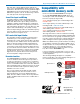
About Digital Hybrid Wireless
®
All wireless links suffer from channel noise to some
degree, and all wireless microphone systems seek to
minimize the impact of that noise on the desired signal.
Conventional analog systems use compandors for
enhanced dynamic range, at the cost of subtle artifacts
(known as “pumping” and “breathing”). Wholly digital
systems defeat the noise by sending the audio informa-
tion in digital form, at the cost of some combination of
power, bandwidth, operating range and resistance to
interference.
The Lectrosonics Digital Hybrid Wireless
system over-
comes channel noise in a dramatically new way, digitally
encoding the audio in the transmitter and decoding it
in the receiver, yet still sending the encoded informa-
tion via an analog FM wireless link. This proprietary
algorithm is not a digital implementation of an analog
compandor but a technique which can be accomplished
only in the digital domain.
Since the RF link between transmitter and receiver is
FM, channel noise will increase gradually with in-
creased operating range and weak signal conditions,
however, the Digital Hybrid Wireles system handles this
situation elegantly with rarely audible audio artifacts as
the receiver approaches its squelch threshold.
In contrast, a purely digital system tends to drop the
audio suddenly during brief dropouts and weak signal
conditions. The Digital Hybrid Wireless
system simply
encodes the signal to use a noisy channel as efficiently
and robustly as possible, yielding audio performance
Table of Contents
Introduction ............................................................................ 2
About Digital Hybrid Wireless
® ...............................................................................2
Servo Bias Input and Wiring ................................................ 3
DSP-controlled Input Limiter ................................................ 3
Recorder function ................................................................. 3
Compatibility withmicroSDHC memory cards .................... 3
Features .................................................................................. 4
Battery Status LED Indicator ............................................... 4
Menu Shortcuts .................................................................... 4
IR (infrared) Sync ................................................................. 4
Battery Installation ............................................................... 5
Formatting SD Card ............................................................... 5
IMPORTANT .......................................................................... 5
iXML HEADER SUPPORT .................................................. 5
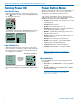
Turning Power ON ................................................................. 6
Short Button Press ............................................................... 6
Long Button Press ............................................................... 6
Menu Shortcuts .................................................................... 6
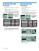
Transmitter Operating Instructions ..................................... 7
Recorder Operating Instructions ......................................... 7
SMWB Main Menu .................................................................. 8
SMWB Power Button Menu ................................................... 9
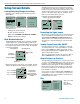
Setup Screen Details ............................................................ 10
Locking/Unlocking Changes to Settings............................... 10
Main Window Indicators ....................................................... 10
Connecting the Signal Source ............................................. 10
Turning Control Panel LEDs ON/OFF .................................. 10
Helpful Features on Receivers ............................................. 10
Files ..................................................................................... 10
Record or Stop .................................................................... 11
Adjusting the Input Gain ....................................................... 11
Selecting Frequency ............................................................ 11
Selecting Frequency Using Two Buttons .............................. 12
About Overlapping Frequency Bands .................................. 12
Selecting the Low Frequency Roll-off .................................. 12
Selecting the Compatibility (Compat) Mode ......................... 12
Selecting Step Size .............................................................. 13
Selecting Audio Polarity (Phase) .......................................... 13
Setting Transmitter Output Power ........................................ 13
Setting Scene and Take Number ......................................... 13
Choosing Takes for Replay .................................................. 13
Recorded File Naming ........................................................ 13
SD Info ................................................................................. 13
Restoring Default Settings ................................................... 13
5-Pin Input Jack Wiring ......................................................... 14
Microphone Cable Termination
for Non-Lectrosonics Microphones .............................. 15
Input Jack Wiring for Different Sources .............................. 16
Microphone RF Bypassing ................................................... 17
Line Level Signals ................................................................ 17
Firmware Update ................................................................... 18
Recovery Process ................................................................. 19
Declaration of Conformity..................................................... 19
Silver Paste on SM Series Transmitter Thumbscrews ........ 20
Straight Whip Antennas ........................................................ 21
Belt Clips and Pouches ......................................................... 22
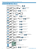
DBSM Single Battery Model ................................................ 22
DBSMD Dual Battery Model ................................................ 22
Miscellaneous Accessories .................................................. 23
LectroRM ................................................................................ 24
Specifications ........................................................................ 25
Troubleshooting ..................................................................... 26
Service and Repair ................................................................ 28
Returning Units for Repair ................................................... 28