
User's Manual


DSW Digital Wireless System
Rio Rancho, NM
7
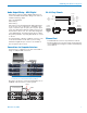
Audio Output Wiring - AES3 Digital
XLR output connectors deliver digital audio that con-
forms to the AES standard. The wiring is the same as
a balanced analog output.
Pin 1 Ground/Shield
Pin 2 Data (+)
Pin 3 Data (–)
Pins 2 and 3 carry the digital audio. Although polarity
is not an issue, it is good practice to maintain a “pin
to pin” connection - pin 1 to pin 1, pin 2 to pin 2, pin 3
to pin 3 in cables that terminate in XLR connectors at
both ends. It is best to use 110 ohm cable designed to
carry digital signals. Conventional microphone cables
may cause problems, especially with distances over 30
or 40 feet.
For pinout details of wiring to a DB-25 connector, refer
to the documentation for the device you are using.
Channel assignments per connector are marked on
the rear panel of the receiver.
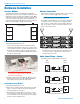
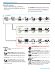
Connections for Computer Interface
Connection to a computer for set up is easiest with a
single or multiple USB connection.
USB Hub
NOTE: Audio is not passed through the USB port. It
is used only for control and monitoring settings.
Receivers can also be connected via RS-232 ports on
PCMCIA cards and remote control systems.
( )
( )
AES
WORD
CLOCK
ANT
PWR
AES
5 & 6
AES
3 & 4
AES
1 & 2
ANT
PWR
( )
( )
AES
WORD
CLOCK
ANT
PWR
AES
5 & 6
AES
3 & 4
AES
1 & 2
ANT
PWR
Control System
Com 1
Com 2
RS-232 Port Pinouts
1
2
3
4
5
6
7
8
9
1
2
3
4
5
6
7
8
9
DCD
RX
TX
DTR
GND
DSR
RTS
CTS
RI
TX
RX
GND
Host
Serial
Port
(PC)
DR
RS-232
Port
DTE pin
functions
Female
connector
Male
connector
DCE pin
functions
Female
jack
Male jack
Ethernet Port
A standard RJ-45 connector is provided for network
interfacing. This port is used for setup, monitoring and
control with Wireless Designer software and third party
control devices.