
User's Manual


DSW Digital Wireless System
LECTROSONICS, INC.
6
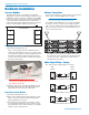
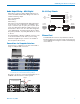
Antenna Connections
Connect the antennas or coaxial cables to the antenna
input connectors labeled IN on the rear panel.
Note: The frequency bandwidth of the antennas
must cover the range of the modules in use.
For multiple unit installations, a “loop thru” is available
to feed two or three receivers from a single antenna
pair. Connect coaxial cables from the multicoupler out-
puts on the first receiver to the antenna inputs on the
next receiver in the stack.
( )
( )
AES
WORD
CLOCK
ANT
PWR
AES
5 & 6
AES
3 & 4
AES
1 & 2
ANT
PWR
( )
( )
AES
WORD
CLOCK
ANT
PWR
AES
5 & 6
AES
3 & 4
AES
1 & 2
ANT
PWR
( )
( )
AES
WORD
CLOCK
ANT
PWR
AES
5 & 6
AES
3 & 4
AES
1 & 2
ANT
PWR
The upper connectors are the inputs connected to
the antennas on the first unit in the stack. The lower
connectors are the outputs that feed the next as-
sembly lower in the rack.
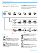
Audio Output Wiring - Analog
The analog audio output wiring is as follows:
(+)
1
(-)
SHIELD
SHIELD
(+)
(-)
2
3
(+)
1
(-)
SHIELD
SHIELD
(+)
2
3
(+)
1
(-)
SHIELD
SHIELD
(+)
2
3
DR
Output
Audio
Input
Balanced with 3-wire cable
Unbalanced with 3-wire cable
Unbalanced with 2-wire cable
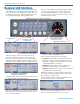
Hardware Installation
Receiver Modules
The DR mainframe/host assembly is a wideband
design that coves the entire available frequency range.
Individual receiver modules are available in 25.6 MHz
frequency “blocks.” Any module can be installed in any
of the six mainframe positions without regard to the
frequency tuning range. Module positions correspond
to the rear panel audio outputs as shown here.
Front panel
1
2
3
4
5
6
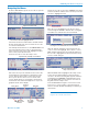
Installing Receiver Modules
1. Turn the mainframe power off.
The receiver modules interface with the main as-
sembly through multi-pin connectors on either side
of the chassis. Insert the module straight down and
then slide it toward the main housing to insert the
connector pins. The module should sit flush against
the side of the housing.
Retaining clip
Caution: Make sure the connectors align
correctly. Do not apply excessive force to seat
the module onto the tab.
2. Align the ridge on the retaining clip with the slot in
the chassis and press the clip downward until the
ridge snaps into the slot in the side panel.
Removing Receiver Modules
1. Turn the mainframe power off.
2. Remove the retaining clip by pressing the top side-
ways to release it from the slot in the side panel.
Then pull upward to remove it.
3. Pull outward on the module to release the connec-
tor and then lift it upward out of the chassis. Holes
in the underside of the chassis allow you to grip the
module on the top and bottom.