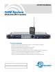
INSTRUCTION MANUAL DSW System DR Receiver/DB Transmitter Essential Setup Steps 1) Install receiver modules, antennas and connect to a power supply (see page 6) 2) Generate an encryption key (see page 20) 3) Install transmitter batteries and antennas (see page 15) 4) Transfer encryption key to transmitters (see page 20) 5) Identify and set operating frequencies on the receiver using Smart TuneTM (see page 21) (the procedure includes transferring frequency settings to the transmitters) 6) Attach microphone
DSW Digital Wireless System 2 LECTROSONICS, INC.
DSW Digital Wireless System Table of Contents Essential Setup Steps ..........................................................1 Introduction............................................................................3 Receiver Front Panel .............................................................4 Headphone output ...............................................................4 LCD and control Interface ....................................................4 Encryption key and settings transfer port......
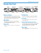
DSW Digital Wireless System Receiver Front Panel LCD and control inferface for system setup Headphone output Rotary encoder Encryption key and settings transfer port USB port Comm Alert LED Power LED LED Headphone output A standard 1/4 inch jack and volume control knob LCD and control Interface All settings for the receiver and transmitter can be adjusted from the receiver front panel.
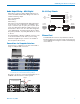
DSW Digital Wireless System Receiver Rear Panel Antenna input A Audio outputs channels 4 - 6 Digital audio word clock ports AES WORD CLOCK ANT PWR AES output channels AES 3&4 Ethernet port Antenna connections Standard 50 ohm BNC jacks accept input from the antennas. A built-in multi-coupler distributes the antenna signal to the six receiver modules, and also to the OUT jack to deliver the signal to an additional receiver. Audio Outputs Each XLR connector provides a balanced analog output.
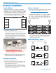
DSW Digital Wireless System Hardware Installation Receiver Modules Antenna Connections The DR mainframe/host assembly is a wideband design that coves the entire available frequency range. Individual receiver modules are available in 25.6 MHz frequency “blocks.” Any module can be installed in any of the six mainframe positions without regard to the frequency tuning range. Module positions correspond to the rear panel audio outputs as shown here.
DSW Digital Wireless System Audio Output Wiring - AES3 Digital RS-232 Port Pinouts XLR output connectors deliver digital audio that conforms to the AES standard. The wiring is the same as a balanced analog output. Pin 1 Ground/Shield Pin 2 Data (+) Pin 3 Data (–) Pins 2 and 3 carry the digital audio. Although polarity is not an issue, it is good practice to maintain a “pin to pin” connection - pin 1 to pin 1, pin 2 to pin 2, pin 3 to pin 3 in cables that terminate in XLR connectors at both ends.
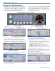
DSW Digital Wireless System Receiver LCD Interface All settings can be made from the front panel keypad and LCD interface, including transmitter settings if it is connected to the receiver with the key cable. The control interface consists of membrane switches, a rotary encoder with push switch and a graphical LCD. Press one of the numbered switches under the display to open a setup screen for the corresponding channel. Press the BACK button to return to the previous screen.
DSW Digital Wireless System Navigating the Menus From the Main Window, press the encoder to open the menu select screen. Rotate the encoder to select the “CHOOSE” item in the lower bar (markers indicate active selection). Press the encoder to highlight the item. Top bar lists active menu Once the icon is highlighted, rotate the encoder to scroll through the available channels. The rectangular icon will move to indicate the selected channel.
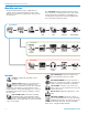
DSW Digital Wireless System Menu Map and Icons Receiver and transmitter setup or adjustments to settings can be completed using the receiver LCD interface. The menus are organized into three groups, as shown here. The TOP MENU includes system setup and connections, frequency scanning and selection, and encryption key generation and transfer to transmitters for overall system setup. Links to the TX and RX menus are located at the leftmost position.
DSW Digital Wireless System The TX MENU (transmitter menu) is used to configure and store the settings for all transmitters that will be used in the system. These settings, stored in the receiver memory, can be transferred from the receiver to the transmitter during setup with the key cable. A link back to the Top Menu is located at the leftmost position. RX MENU (receiver menu) includes menu items for each receiver module to set up operating parameters and options.
DSW Digital Wireless System (TX MENU cont’d) LF ROLLOFF adjusts the point at which the low frequency audio in the transmitter begins to roll off. This “knee” can be set at 35, 50, 70, 100, 120 or 150 Hz. TX PHASE reverses the polarity of the audio signal in the transmitter to match other microphones in the system that vary with different microphone types and connector wiring. NOTE: The audio polarity on each output channel on the receiver can also be reversed in the RX MENU.
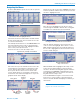
DSW Digital Wireless System Software Installation The supplied software for the DSW system is available on disk or downloaded from the web site at: Click on Next to continue. Installation with downloaded file: www.lectrosonics.com/wdsupport The software will run on Windows or Mac computers. The procedure for installing it varies between downloaded and disk versions. Windows Installation NOTE: Uninstall any previous version before installing this software.
DSW Digital Wireless System Mac Installation Launch your browser and go to: http://lectrosonics.com/wdsupport/xap/WirelessDesigner.html When the Wireless Designer intro screen appears, right click and choose Install Wireless Designer onto this computer... Connecting to a Network Using DHCP for IP Address Assignment Follow these steps to make a network connection for the receiver: 1) Open Wireless Designer and connect to the receiver via USB. 2) Click on Settings in the left pane.
DSW Digital Wireless System DB Transmitter Battery status LED Features and Functions The keypad and LCD interface provides access to settings and adjustments. A toggle switch on the top panel is programmable to operate as an audio mute switch, a power switch or be inoperative. This allows the transmitter to be configured with full access to all settings, or as a simple one-button device with settings locked. The transmitter is powered by three AA batteries in series.
DSW Digital Wireless System Powering On in Operating Mode Power Menu Press and hold the Power Button until a counter on the LCD progresses from 1 to 3. When you release the button, the unit will be operational with the RF output turned on and the Main Window displayed. Hold for Rf On ...3 RF indicator Steve s AutoOn? opens a dialogue screen with options to either automatically restore power after batteries have been replaced, or leave the unit turned off after batteries have been replaced. 494.
DSW Digital Wireless System Navigating Menus Selecting Programmable Switch Functions The LCD/keypad interface makes it easy to browse the menus and make the selections for the setup you need. When the unit is powered up in either the operating or the standby mode, press MENU/SEL on the keypad to enter a menu structure on the LCD. Use the and arrow buttons to select the menu item. Then press the MENU/SEL button to enter the menu. Gain Gain Freq.
DSW Digital Wireless System DB Transmitter Menu Map From the main window, navigate with the arrow buttons to the desired menu item and press MENU/SEL to enter the setup screen. Gain SEL BACK Gain 22 Level meter at bottom of screen Freq. Freq. ProgSw Rolloff Phase SEL BACK 470.
DSW Digital Wireless System Copying Transmitter Settings To and From the Receiver Connect the key cable from the jack labeled KEY on the front of the receiver to the micro USB port on the side of the transmitter. If transmitter settings are defined in the receiver, they can be transferred to a connected transmitter, or copied from a transmitter to a receiver channel using the key cable.
DSW Digital Wireless System System Setup These instructions apply to setup using the front panel LCD. If you will be using Wireless Designer for setup, instructions are in the help files supplied with the software. Select the NEW KEY option and press the encoder to enter the setup screen. Install Receiver Modules Turn power off on the DR mainframe. Install the modules as needed. Any module can be installed in any position in the mainframe assembly.
DSW Digital Wireless System Frequency Selection Manual selection may be necessary if frequencies are mandated by an authority, such as a major sporting event. You can manually set the frequencies and settings for the transmitters in the receiver, then connect a transmitter and transfer settings. Or, of course, just manually set the frequency in each receiver channel and transmitter. After adjusting the frequency, press the BACK button on the front panel or the encoder to de-highlight the item.
DSW Digital Wireless System Select BEGIN in the setup screen and press the encoder to start the process. Scanning will proceed one at a time on each receiver, from the lowest numbered one to the next higher numbered one. Attach Microphone and Adjust Transmitter Gain This adjustment is very important to optimize the signal to noise ratio and dynamic range that the system is capable of delivering.
DSW Digital Wireless System Adjust Receiver Analog Audio Output Level The analog audio output of the receiver is set at maximum, and lower levels are achieved with an attenuator to reduce the signal level to match the level requirements of other equipment. This means that there is no difference in signal to noise ratio regardless of where the receiver output level control is set. Any time gain is applied to the audio signal, noise is also added.
DSW Digital Wireless System Specifications System Operating Frequencies: Sampling Size and Rate: Digital Modulation: Symbol rate: Data Compression: Encryption: System Latency: Audio Frequency Response: Distortion: Dynamic Range: 470.100 - 691.175 MHz in 25 kHz steps 24-bit, 48 kHz 8PSK 128 k Proprietary ADPCM AES 256-CTR (per FIPS 197 and FIPS 140-2) 2.5 ms 20 - 20 kHz, +/- 1 dB 0.
DSW Digital Wireless System Service and Repair If your system malfunctions, you should attempt to correct or isolate the trouble before concluding that the equipment needs repair. Make sure you have followed the setup procedure and operating instructions. Check the interconnecting cables and then go through the Troubleshooting section in this manual.
DSW Digital Wireless System FCC Notice NOTE: This equipment has been tested and found to comply with the limits for a Class B digital device, pursuant to Part 15 of the FCC Rules. These limits are designed to provide reasonable protection against harmful interference in a residential installation. The equipment generates, uses and can radiate radio frequency energy and, if not installed and used in accordance with the instructions, may cause harmful interference to radio communications.
DSW Digital Wireless System Rio Rancho, NM 27
LIMITED ONE YEAR WARRANTY The equipment is warranted for one year from date of purchase against defects in materials or workmanship provided it was purchased from an authorized dealer. This warranty does not cover equipment which has been abused or damaged by careless handling or shipping. This warranty does not apply to used or demonstrator equipment. Should any defect develop, Lectrosonics, Inc. will, at our option, repair or replace any defective parts without charge for either parts or labor.