INSTRUCTION MANUAL D4 Digital Wireless System Fill in for your records: Serial Number: Purchase Date: Rio Rancho, NM, USA www.lectrosonics.
D4T/D4R 2 LECTROSONICS, INC.
4-channel Digital Wireless System Table of Contents Introduction.............................................................................3 General Technical Description..............................................4 Front and Rear Panels............................................................6 Navigating the LCD................................................................7 Antenna Placement and Orientation.....................................7 TransmitterGeneral Settings.........................
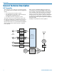
D4T/D4R General Technical Description D4T Transmitter The transmitter can accept up to four inputs from digital or analog sources. The inputs can be configured as follows: • Four analog inputs using all four jacks • Two digital inputs using jack 1 and two balanced analog inputs using jacks 3 and 4 • Four digital channels using jacks 1 and 2 The input connectors are TA3 “mini XLR” types with the same pin numbering as standard XLR connectors for AES/EBU and balanced line level analog signals.
4-channel Digital Wireless System D4R Receiver The receiver employs two complete RF sections for true diversity reception. The signals from both antennas are independently decoded and error-corrected, and the diversity system uses all digital data and timing reference information from both antennas in order to reconstruct the original audio signals. Audio outputs may be configured for analog balanced or AES/EBU digital signals.
D4T/D4R Front and Rear Panels On both the D4T and the D4R, the front panel interface contains a power switch, an LCD display and eight push buttons. The D4T has one antenna jack and the D4R has two. The D4R front panel also contains a jack for headphones. When the units are powered on, an initial introductory splash screen is displayed; the Main Window then appears and remains on the LCD until a setup screen is selected. The Main Window shows four audio level meters, one for each channel.
4-channel Digital Wireless System Navigating the LCD Navigation through setup screens is the same on the transmitter and receiver. The Main Window will display audio levels for all active channels while the system is operating. Press the FUNC button to enter the setup menu. DIGITAL TRANSMITTER FUNC BACK 1 2 3 Antenna Placement and Orientation The supplied antenna is a center fed half-wave type with a right angle elbow and rotating mount.
D4T/D4R Transmitter General Settings Tuning Menu 2/4 Channel Modes Use UP/DOWN arrows to select menu item and press FUNC to enter setup Use UP/DOWN arrows to select frequency, then press FUNC to return to menu Use UP/DOWN arrows to select menu item and press FUNC to enter setup Audio Trim Use UP/DOWN arrows to select menu item and press FUNC to enter setup Locked/Unlocked Modes The front panel controls can be locked to prevent inadvertent changes to the selected settings.
4-channel Digital Wireless System Transmitter Audio Trim Setup From the Main Window, press FUNC and then select the menu item “Audio Trim” and press FUNC again. The setup screen will vary slightly depending upon which AES3 mode has been selected and whether the 2-channel or 4-channel mode is selected. In the 2-channel mode, channels 3 and 4 will be blank.
D4T/D4R Receiver General Settings AES3 Modes Use UP/DOWN arrows to select menu item and press FUNC to enter setup Tuning Selection Use UP/DOWN arrows to select menu item and press FUNC to enter setup Use UP/DOWN arrows to select frequency, then press FUNC to return to menu Use UP/DOWN buttons to select desired mode Audio Level Use UP/DOWN arrows to select menu item and press FUNC to enter setup 2/4 Channel Modes NOTE: The setup screens for audio level will be different depending upon the
4-channel Digital Wireless System Locked/Unlocked Modes The front panel controls can be locked to prevent inadvertent changes to the selected settings. When the panel is Locked, settings can be viewed but not changed, with the exception of headphone selection and monitoring level controls. Use UP/DOWN arrows to select menu item and press FUNC to enter setup Receiver Audio Level Setup From the Main Window, press FUNC and then select the menu item Audio Lev. and press FUNC again.
D4T/D4R Transmitter AES3 Modes The transmitter can be set up in three different configurations with the AES3 modes menu for 4-channel operation: ANALOG CH 1 DIGITAL DIGITAL CH 1 DIGITAL DIGITAL CH 1 ANALOG CH 2 NOT USED CH 2 DIGITAL DIGITAL CH 2 ANALOG CH 3 ANALOG CH 3 NOT USED CH 3 ANALOG CH 4 ANALOG CH 4 NOT USED CH 4 Two different configurations are available for 2-channel operation: ANALOG CH 1 DIGITAL DIGITAL CH 1 ANALOG CH 2 NOT USED CH 2 NOT USED CH 3 NOT USED CH 3
4-channel Digital Wireless System Frequency Selection Finding Clear Frequencies Frequencies are arranged into four groupings as shown below, with each grouping containing one 4-channel frequency and two 2-channel frequencies. In the 4-channel mode (4 audio channels) one of four different frequencies may be selected, each containing four audio channels. In the 2-channel mode (2 audio channels) one of eight frequencies may be selected, each containing two audio channels.
D4T/D4R Parts and Accessories Transmitter Power Supples Receiver Power Supplies • Lectrosonics DCR12/A8U (Replacement Power Supply) Power Supply for D4T & D4R; 100-240 VAC, 50/60 Hz input; 12 VDC (regulated), 800 mA max. output. • Lectrosonics DCR12/A8U (Replacement Power Supply) Power Supply for D4T & D4R; 100-240 VAC, 50/60 Hz input; 12 VDC (regulated), 800 mA max. output.
4-channel Digital Wireless System Power Adapter Cables Antenna • 21747 right angle, locking plug with 6 ft. cable to stripped and tinned leads. Supplied with the transmitter and receiver. • AMJR-915 adjustable antenna for D4R and D4T. Supplied with transmitter and receiver (reverse gender SMA connector). Supplied with the transmitter and receiver • 21746 right angle, locking plug with 12 inch cable to stripped and tinned leads.
D4T/D4R Firmware Updates As new versions of the firmware become available, updates are accomplished with a software utility and simple procedure. In many cases, updates must be made to both transmitter and receiver to ensure compatibility and provide the latest feature set. The software interface operates with Windows 2000, XP and Vista operating systems. Configuring the USB Port 1) Remove any previous LecNet2 installation from your computer. 2) Install LecNet2 software.
4-channel Digital Wireless System Specifications Overall System Operating Spectrum: Center Frequencies (MHz): 4-channel Mode: Center Frequencies: (MHz): 2-channel Mode: Modulation Type: Occupied Bandwidth: Audio Sampling: Latency (overall system): Digital In/Digital Out: Analog In/Analog Out: Selectable Audio Channels: Audio Performance (overall system): Frequency Response: THD+N: Dynamic Range: Adjacent Channel Isolation: 902 - 928 MHz 907.776, 912.384, 916.992, 923.
D4T/D4R Service and Repair If your system malfunctions, you should attempt to correct or isolate the trouble before concluding that the equipment needs repair. Make sure you have followed the setup procedure and operating instructions. Check the interconnecting cables and then go through the Troubleshooting section in this manual. We strongly recommend that you do not try to repair the equipment yourself and do not have the local repair shop attempt anything other than the simplest repair.
LIMITED ONE YEAR WARRANTY The equipment is warranted for one year from date of purchase against defects in materials or workmanship provided it was purchased from an authorized dealer. This warranty does not cover equipment which has been abused or damaged by careless handling or shipping. This warranty does not apply to used or demonstrator equipment. Should any defect develop, Lectrosonics, Inc. will, at our option, repair or replace any defective parts without charge for either parts or labor.