
User Manual
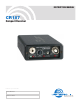


Compact Receiver
Table of Contents
Introduction.............................................................................................................................................................................................4
General Technical Description ..............................................................................................................................................................4
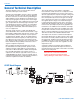
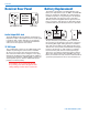
CR187 Block Diagram...........................................................................................................................................................................4
Controls and Functions .........................................................................................................................................................................5
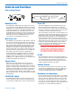
Receiver Front Panel ..............................................................................................................................................................................5
Modulation LEDs...................................................................................................................................................................................5
Output Control.......................................................................................................................................................................................5
EXT/OFF/INT Switch ............................................................................................................................................................................5
Power LED............................................................................................................................................................................................5
RF LED .................................................................................................................................................................................................5
Receiver Rear Panel ...............................................................................................................................................................................6
12 VDC Input.........................................................................................................................................................................................6
Audio Output XLR Jack.........................................................................................................................................................................6
Mini Phone Jack....................................................................................................................................................................................6
Antenna Terminal ..................................................................................................................................................................................6
Battery Replacement..............................................................................................................................................................................7
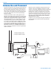
Antenna Use and Placement .................................................................................................................................................................8
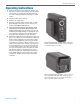
Operating Instructions...........................................................................................................................................................................9
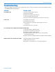
Troubleshooting......................................................................................................................................................................................9
Replacement Parts and Accessories..................................................................................................................................................10
Specifications and Features................................................................................................................................................................10
Service and Repair ...............................................................................................................................................................................11
Returning Units for Repair ..................................................................................................................................................................11
Introduction
The CR187 receiver design originated in the late 1980’s with a feature set intended for camera mounted ENG appli-
cations. It’s fixed frequency design included extremely sharp front-end filters and narrowband crystal filters in the IF
stage, which likely explains its continued use in today’s crowded RF environment.
The receiver operates on a single 9V battery or external DC power, allowing it to be used in a wide variety of applica-
tions in broadcast and film production, ENG and with almost any pro sound equipment.
Rio Rancho, NM
3