CR185 COMPACT RECEIVER OPERATING INSTRUCTIONS and trouble-shooting guide LECTROSONICS, INC.
INTRODUCTION Thank you for selecting the Lectrosonics Professional Series wireless microphone system. This system represents well over 10 years of manufacturing experience in wireless microphones, and almost 70 years of design experience. The CR185 receiver design is the result of surveying the needs of professional video producers, ENG cameramen and many others in the broadcast and pro video industry. Hundreds of conversations with dealers and end-users developed the final parameters for the design.
GENERAL TECHNICAL DESCRIPTION The CR185 receiver is comprised of six major functional subsystems: the RF front-end amplifier, the double balanced mixer/local oscillator, the first IF filter, the second IF filter and audio demodulator, the compandor, and the balanced microphone level output circuit. The RF front-end amplifier consists of three cascaded pairs of helical resonators for high selectivity.
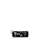
CONTROLS AND FUNCTIONS RECEIVER FRONT PANEL MODULATION LEDs Indicate the modulation (audio level) of the incoming signal, and can be used for proper adjustment of the transmitter’s "MIC LEVEL" or "GAIN". The -20 LED glows when the transmitter modulation is at a high enough level to produce a good audio signal-to-noise ratio. It will normally flicker, or stay lit as you speak into the microphone. The 0dB lamp indicates a "peak," showing that the transmitter modulation is at maximum.
CONTROLS AND FUNCTIONS Since the internal circuits are all tightly regulated the receiver will continue to operate to a battery voltage of 6.5 volts. From 6.5 volts to 6 volts, the receiver will still operate, but with degraded performance. Below 6 volts, the regulated and temperature compensated squelch circuit will cease to be regulated. The result is that the squelch circuit will remain "open".
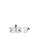
RECEIVER REAR PANEL 12 VDC INPUT Connects to the supplied CH-12 AC adapter for powering the receiver from a 110/120V AC source. The receiver may also be powered from external 12 volt DC sources using the correct plug (Switchcraft S-760 power plug). A diode bridge is used in the external power input, so that the CR185 will operate properly from either polarity. AUDIO OUTPUT Supplies a balanced, low impedance output at microphone level. The audio signal is output on pins 2 and 3, while pin 1 is ground.
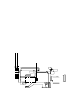
ANTENNA USE AND PLACEMENT Connect the antenna to the front panel jack. Position the antenna so that it is not within 3 or 4 feet of large metal surfaces. If this is not possible, try to position the antenna so that it is as far away from the metal surface as is practical. It is also good to position the receiver so that there is a direct "line of sight" between the transmitter and the receiver antenna.
OPERATING INSTRUCTIONS 1) Connect the power cord or install the battery. 2) Attach and extend the antenna. 3) Connect the audio cable. 4) Set the front panel switch to either "EXT" or "INT", depending upon the power source. Check to see that the red POWER LED lights up. 5) THIS IS PERHAPS THE MOST IMPORTANT STEP IN THE SET UP PROCEDURE. Adjust the transmitter "gain".
TROUBLESHOOTING Before going through the following chart, be sure that you have a good battery in the receiver (or a properly connected AC adapter). The POWER LED should glow brightly.
SERVICE AND REPAIR If your system malfunctions, you should attempt to correct or isolate the trouble before concluding that the equipment needs repair. Make sure you have followed the setup procedure and operating instructions. Check out the inter-connecting cords and then go through the TROUBLE SHOOTING section in the manual We strongly recommend that you do not try to repair the equipment yourself and do not have the local repair shop attempt anything other than the simplest repair.
SPECIFICATIONS AND FEATURES Operating Frequencies: 150MHz to 216MHz, crystal controlled Sensitivity: Better than 0.6uV for 20dB quieting without compandor; 1.9uV for 50dB S/N ratio with compandor Signal/Noise Ratio: 102dB unweighted; 109dB A-weighted Squelch Quieting: greater than 100dB AM Rejection: -60dB (10uV to 0.1 Volts) Modulation Acceptance: ±15kHz Image and Spurious Rejection: greater than 100dB Third Order Intercept: +6dBm Audio Outputs: XLR: 200 Ohms balanced; 100mV max.
LIMITED ONE YEAR WARRANTY The equipment is warranted for one year from date of purchase against defects in materials or workmanship provided it was purchased from an authorized dealer. This warranty does not cover equipment which has been abused or damaged by careless handling or shipping. This warranty does not apply to used or demonstrator equipment. Should any defect develop, we will, at our option, repair or replace any defective parts without charge for either parts or labor.