
User's Manual


UCR411A
LECTROSONICS, INC.
8
applied to remove most of the hiss from the mic preamp
and some of the hiss from lavaliere microphones. The
noise reduction benefit is dramatic in this position, yet
the degree of transparency maintained is exceptional.
When switched to FULL, enough noise reduction is ap-
plied to remove most of the hiss from nearly any signal
source of reasonable quality, assuming levels are set
properly at the transmitter. This additional noise reduc-
tion comes at the cost of some transparency for low-lev-
el room noise, yet the algorithm remains undetectable
under most circumstances.
Audio Output Level
A setup screen is provided for adjusting the audio out-
put level in 1 dB increments from -50 to +5 dBu using
the front panel SEL Up and Down buttons.
Test Tone
To assist in matching the audio levels of equipment con-
nected to the UCR411A, a 1 kHz audio test tone, adjust-
able from -50 to +5 dBu in 1 dB increments, is available
at the XLR connector. This tone is available through the
TONE display window.
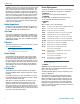
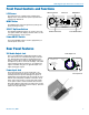
Batteries
The UCR411A operates on two 9 Volt alkaline or LiPoly-
mer rechargeable batteries.
NOTE: Do not use an alkaline and a LiPolymer
rechargeable in the same unit. Standard or “heavy
duty” batteries are not recommended.
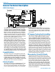
Power Supply
The UCR411A may be operated from an external DC
power source (see Specifications and Features section
for allowed voltages.) The receiver has a built-in Poly-
Fuse to protect the unit. This fuse automatically resets if
the power supply is disconnected for about 15 seconds.
The power section also has protection circuits that pre-
vent damage to the receiver if a positive ground power
source is applied.
LCD Display
The display has four primary windows. Pressing the
Front Panel MENU button steps through each of these
windows.
If the battery gets low on either transmitter or receiver,
a message will interrupt the display every few seconds
and flash a low battery warning.
After power is turned off and back on again, the unit
defaults to the Main window and to the most recent
frequency, audio level, transmitter battery type and
other user settings. These settings are retained even if
the batteries are removed. After five minutes of no key
activity, the LCD backlight times out and reverts back to
last screen used when reactivated.
Power Up Sequence
The power up sequence consists of four messages that
appear automatically after the power is switched on.
1) UCR411A
BLK xx (xx is the frequency block number)
2) VERSION
R.R/A.A (R.R is the RF board firmware version,
A.A is the audio board firmware version)
3) COMPAT
XXX
Where “XXX” is one of the following:
NA 400 North American - Native 400 Series Digital Hybrid mode
NA 100 Lectrosonics 100 Series compatibility
NA 200 Lectrosonics 200 Series compatibility
NA M3 Compatible with certain non-Lectrosonics transmitters
NA IFB Compatible with all Lectrosonics IFB transmitters.
NA M6 Compatible with certain non-Lectrosonics transmitters
NA M7 Compatible with certain non-Lectrosonics transmitters
EU HBR European Union - Native 400 Series Digital Hybrid mode
EU 100 European Union - 100 Series compatibility
EU 200 European Union - 200 Series compatibility
EU M3 European Union - Compatible with certain
non-Lectrosonics transmitters
EU IFB European Union - Compatible with all Lectrosonics
IFB transmitters.
EU M6 European Union - Compatible with certain
non-Lectrosonics transmitters
EU M7 European Union - Compatible with certain
non-Lectrosonics transmitters
Note: NA M7 & EU M7 are only available with firmware
6.0 on the audio board.
4) TUNING
NORMAL Tune in single channel increments.
GRP x Tune in pre-coordinated intermod-free frequen-
cies (x is A, B, C, D, U or V)
The Main Window appears after the introductory mes-
sages are displayed.
The UCR411A is fully operational during the power
up sequence and will immediately respond to button
pushes made before the automatic sequence is com-
pleted. If a valid transmitter signal is already present
when the receiver is turned on, the audio output will
typically be engaged somewhere in the middle of the
power-up sequence, following a brief delay to allow the
audio circuits to stabilize.