
User's Manual

UCR411A
LECTROSONICS, INC.
16
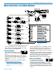
Installation and Operating Instructions
1. Install a fresh battery or connect an external power
source to the UCR411A and attach the antennas.
2. Unless frequency settings have been previously
assigned, scan for an open frequency and set both
the receiver and transmitter to that frequency. (See
Finding Clear Frequencies.)
3. Connect the audio cable to the Receiver Audio Out
XLR jack.
4. Set the Power ON/OFF switch to ON and verify that
the LCD panel activates.
5. Adjust the transmitter gain.
THIS IS PERHAPS THE MOST IMPORTANT STEP
IN THE SET UP PROCEDURE. Refer to your
transmitter manual’s Operating Instructions section
for details on how to adjust the transmitter gain. In
general, adjust the transmitter gain so that the voice
peaks will cause the audio modulation indicators on
the receiver and transmitter to show full modulation
on the loudest peak audio levels. Normal levels
should cause the UCR411A’s audio level icon to
fluctuate fully. This will result in the best possible
signal to noise ratio for the system.
Important:
• Adjustthetransmittergainbefore you adjust the
receiver output level.
• Whenthetransmitteriffullymodulated,itslimiter
will prevent any further increases in level.
• Thereceiveroutputcircuitryissettorunatfull
output, and the level control is simply an attenuator.
There is no difference in signal to noise ratio across
the entire adjustment range of the receiver output
level. The transmitter input gain is the critical adjust-
ment that will affect the signal to noise ratio.
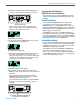
6. Adjust the Audio Output according to the type of
input on your equipment. Use the LEVEL menu
and adjust the level with the SELECT Up and Down
buttons.
The input levels of different cameras, VCRs, and PA
equipment vary, which may require that you adjust
the AUDIO OUT to an intermediate position. Try dif-
ferent settings and listen to the results. If the output
of the receiver is too high, you may hear distor-
tion or a loss of the natural dynamics of the audio
signal. If the output is too low, you may hear steady
noise (hiss) along with the audio. The UCR411A
audio output is designed to drive any audio input
device from microphone level to +10dBu line level.
Note: The test tone output is especially useful for
an exact level match. With the test tone running,
adjust for the maximum desired peak level using
the metering on the connected device.
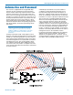
Finding Clear Frequencies
The following procedure will help you identify RF sig-
nals in the area and find clear channels for operating
the wireless system.
1. Ensure transmitter is turned off. Turn on the receiv-
er and wait a few seconds until the Main Window
appears on the LCD
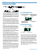
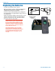
2. Ensure the receiver is NOT in PILOT TONE BY-
PASS mode. (A “P” will be blinking in the upper left
corner of the Main Window.)
Pilot Tone Indicator
TO ENABLE PILOT BYPASS: Step the MENU
key to the MAIN window. Press the MENU and
UP keys together for b bypassed pilot or p normal
pilot.
3. Simultaneously press the MENU and SELECT Up
and Down buttons to enter Scan Mode.
Press all three buttons at the same time and
the receiver will start scanning.
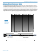
4. View the LCD while the receiver is scanning. The
vertical marker will move across the display from
left to right. RF activity will be indicated by dark
areas in the display.
Vertical marker moves left to right
RF activity