
User's Manual
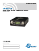


UCR411A
LECTROSONICS, INC.
10
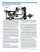
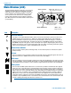
Main Window (LCD)
The Main Window displays information concerning the
condition of the Pilot Tone, antenna phase, RF and
audio signal levels and battery conditions for both the
receiver and the associated transmitter. It is also the
access portal to menu selections for setting up the
receiver and searching for clear frequency channels.
(See Menu Selections from Main window and Frequen-
cy Scan Mode.)
Pilot Tone Indicator
A steady “P” icon will be displayed when a pilot tone from the transmitter is present, in those com-
patibility modes which use pilot tone: 200 Series, Digital Hybrid (400 Series), IFB and Mode 6.
The icon will blink if no pilot tone is present from the transmitter, and it will change to a small “b” if
the pilot tone has been bypassed. To bypass the pilot tone, hold MENU and press the UP button.
Hold MENU and press UP again to restore normal pilot tone squelch. Bypassing the pilot tone also
disables the squelch, so the receiver will produce loud noise when no matching transmitter signal is
being received, regardless of which compatibility mode is selected.
Antenna Phase Indicator
This icon shows antenna phase switching activity. As the antenna phase is switched, the symbol
will flip vertically.
RF Level
This icon changes in size vertically to indicate the strength of the incoming RF signal. RF levels are
engraved from 1uV to 1000uV on the bezel to the left of the LCD display.
Audio Level
This icon changes in size horizontally to indicate the audio level (modulation) of the signal received
from the transmitter. The icon display will change to a solid rectangular block when the audio signal
is being limited in the transmitter. Levels in dB are engraved into the bezel above the LCD display.
Battery Levels
The icon above the Rx symbol indicates the receiver battery condition and will flash when approxi-
mately one hour of operating time is remaining. When external power is being used, the Rx battery
icon changes to look like a power plug. The area above the Tx symbol features either a transmitter
battery status icon or the transmitter battery timer, depending on the TXBAT setting. The transmitter
battery status icon is available only in compatibility modes supporting battery telemetry (400 and
200 Series). In such cases, the transmitter battery status icon appears 5 to 10 seconds after the
transmitter signal is acquired. If selected in the TXBAT setup screen, the transmitter battery timer is
available in any compatibility mode. It accumulates hours and minutes that the communications link
is active, retaining the timing even when the receiver is off.
Note: To reset the battery timer, press and hold MENU and SEL Down together for one second.
Icon
Description
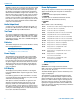
SELECT DOWN Button
SELECT UP Button
MENU Button -
Changes windows
Power ON/OFF
switch
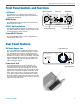
RF level - Top of icon aligns
with value on uV scale
Audio Level - Right side of icon
aligns with value on dB scale