
User manual

Serial Data Debug Solutions
94
919586 RevA
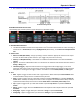
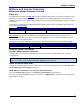
4. AUDIO CHANNEL
Channel - Choose Left or Right as desired.
Bit Order - This field is only enabled when an LJ or RJ variant (step 1, previous) is used. Choose from MSB
(most-significant bit) or LSB (least-significant bit), as desired.
# Bits In Channel - Enter a value using the pop-up numeric keypad for the amount illustrated as follows.
Start Bit - Grayed out field because AudioBus TDM trigger is unavailable.
# Data Bits - Enter a value using the pop-up numeric keypad for the amount illustrated as follows.
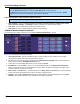
5. SETUP FORMAT - ONLY AVAILABLE FOR DATA TYPE SETUP
Note: This setup sections only appears when the Data type is chosen from the Type (step 3, previous).
Select either Binary or Hexadecimal (Hex) setup mode. The mode selected affects the format of the
following Data Pattern Equals control.
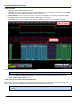
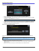
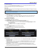
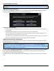
5. MUTE, CLIP, GLITCH, RISING, AND FALLING EDGE SETUP
When Mute, Clip, Glitch, or Rising and Falling Edge types are selected, the Setup Format choices change from
Binary or Hex to Dec and dB buttons (as shown in the following three screen-shots).
Note: These setup sections appear when their corresponding type is chosen from the Type (step 3,
previous).