
User manual


Serial Data Debug Solutions
48
919586 RevA
HIGH SPEED SERIAL TRIGGER SETUP
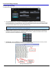
Access the High Speed Serial trigger dialog by touching the Trigger descriptor label, and then the Serial Trigger
button.
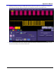
The High Speed Serial trigger dialog is then shown. Notice how the dialog is divided into three sections for
Source Setup, Encoding, and Trigger Patterns.
The remainder of this topic explains these sections and their controls.
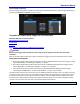
SOURCE SETUP
Click the Compute Bitrate button to find the bitrate of your signal and lock the CDR on the incoming signal. The
Serial Data input must be present on Channel 4 in order to use the Serial Trigger. Verify that the lock is closed
and the correct bitrate has been found before proceeding.
Note: For SDA 820 Zi or higher bandwidth oscilloscopes, channel 3 is used for serial trigger input when
channels 3 and 4 are operating in DBI mode.
The PLL section then indicates that the Phased Locked Loop has locked to your bitrate.
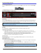
ENCODING
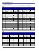
Choose Binary, Hex, or Symbolic (8b/10b) formats for providing your trigger pattern values.
PLEASE NOTE THE FOLLOWING:
Trigger pattern value encoding formats can be changed after providing your entry. Just click on the
format and the conversion is done for you. For example, provide a Hex value on which you would like to
trigger, click the Binary button, and the Hex value is automatically converted into Binary.
Conversions may be done from Hex to Binary, Binary to Hex, Symbolic (8b/10b) to Hex or Binary -
however, Hex or Binary to Symbolic (8b/10b) is not supported.
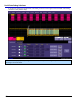
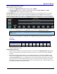
TRIGGER PATTERNS
Now, set the Data Pattern on which to trigger. Binary and Hex data patterns are entered similarly, while
Symbolic 8b/10b differs.
Entering Binary and Hex Data Patterns
You can provide 2 data patterns (80 bit) for triggering. If 2 are used, the system triggers on data pattern 1
OR 2 (indicated on the Trigger On section of the dialog).
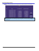
Provide your values by typing directly into the Data Value field, or double-click the field and use the
corresponding pop-up keypad.
Note: Notice how the virtual keypad shown after double-clicking the Data Value field corresponds with
the selected encoding format.
The Highlight Pattern check box may be used to shade the portion of the waveform on the grid display
where your data value occurs.