
User manual


Serial Data Debug Solutions
180
919586 RevA
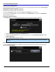
SATA Trigger Setup Detail
The following topic provides specific control settings for a SATA Trigger setup.
PLEASE NOTE THE FOLLOWING:
Most Trigger Setups have some form of Source and Type control.
Only the Symbol Type uses Setup Mode and Symbol Detail controls.
Remaining dialog controls vary based on the selected Pattern Type and are explained in the following
sections.
1. SETUP
Bus Speed - Select the desired bitrate of the connected SATA source from 1.5 Gbps, 3 Gbps, or Auto.
Host Channel - Select the input channel that contains the Host device (C1, 2, 3, or 4). Typically this refers
to the SATA transmitter. If the transmitter is unavailable, select None.
Device Channel - Select the input channel that connects to the SATA device (C1, 2, 3, or 4). This typically
refers to the SATA receiver. If a receiver is not available, select None.
Note: If using two single-ended probes, select the channel that corresponds to the positive terminal.
Direction - Select whether to trigger on the Host or Device.
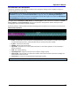
2. FORMAT
Depending on the pattern type, use this control to select either hexadecimal or binary formats.
3. PATTERN TYPE
Pattern Type selections include Symbol, Primitive, FIS Pattern, Data Payload, Protocol Error, and Bus Condition.
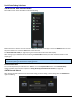
REMAINING DIALOG CONTROLS BASED ON PATTERN TYPE SELECTION
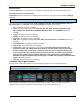
Symbol Pattern Type Selection Controls
With this pattern type selected, triggering is performed on a specified 8B/10B character. Remaining controls on
the dialog vary based on a Symbol Pattern Type selection in the following manner: