
User's Manual
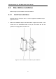
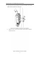
Table Of Contents

LBS7320 Outdoor LTE TDD Base Station User’s Manual
28
4.5.3 Connect RF Cable
1. Open the dust cover on the interface of ANT1, ANT2, ANT3, and ANT4 .
2. Connect one end of the two RF cables to ANT1, ANT2, ANT3, and ANT4
interface of the base station and tighten them with wrench.
3. Winding the waterproof tape.
4. Connect the other end of the RF cables to the external antennas, which also
need waterproof protection.
4.5.4 Connect Optical Fiber
1. Unscrew the screws on the maintenance cavity cover with
3mm L-shape allen
wrench
, and open the maintenance cavity cover.
2. Connect the optical fiber to OPT interface.
3. Laying optical fiber along the pressure clamp, pulling out the maintenance cavity
from the OPT hole.
4. Redundant optical fibers should be wound neatly.
4.5.5 Connect Ethernet Cable
1. Connect the Ethernet cable to ETH interface in the maintenance cavity.
2. Lay Ethernet cable along the pressure clamp, pulling out the maintenance cavity
from the ETH hole.
4.5.6 Connect Power Connector
Power supply mode supports switchboard and AC direct supply.
Since it is impossible to determine the distance between the installation location
and the power supply equipment, operators need to make power cables
according to the actual situation of the installation site .
Switchboard Mode
Peel off the 10mm insulating layer with the cable vice, and connect it to the power fast
plug terminal.