
User's Manual
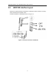
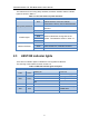
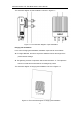
Table Of Contents

LBS7320 Outdoor LTE TDD Base Station User’s Manual
12
The instructions for the wiring cavity interface, the bottom interface and the indicator
lights are shown in table 1-1.
Table 1-1 The instructions of panel interfaces
Identity
Interface
Description
Wiring cavity interfaces
OPT
Optical interface, connect to external
transmission network, used for data backhaul.
ETH
RJ-45 interface, used for debug or data
backhaul.
-48V RTN
Power interface: -48V DC.
Indicator lights
PWR
Used to indicate the running state of the
product. The details are shown in Table 1-1.
RUN
ACT
ALM
Bottom interfaces
ANT1
External antenna 1, N-female connector.
ANT2
External antenna 2, N-female connector.
GPS
External GPS antenna, N-female connector.
2.3 LBS7320 indicator lights
There are four indicator lights to indicate the running state of LBS7320.
The meaning of the indicator is shown in table 1-2.
Table 1-2 LBS7320 indicator lights description
Identity
Color
Status
Description
PWR
Green
Steady On
Power On
Off
No Power Supply
RUN
Green
Fast flash: 0.125s on,0.125s off
Loading
Slow flash: 1s on,1s off
Running
Off
ACT
Green
Steady On
ALM
Red
Steady On
Hardware alarm, e.g.
VSWR alarm
Off
No alarm