
User manual

Littfinski DatenTechnik (LDT)
Operating Instruction
4-fold switch decoder
from the Digital-Professional-Series !
SA-DEC-4-MM-F Part-No.: 210312
(With possible external power supply)
>> finished module <<
Compatible to Märklin-Motorola-Format:
(e.g. Märklin-Digital∼ [Control Unit, Central Station 1
und 2], Intellibox, EasyControl, ECoS, KeyCom-MM,
DiCoStation, EDiTS, EDiTS pro and others)
For digital control of:
⇒ consumers up to 4 Ampere on each output
(e.g. illumination, disconnection of track sections from
power).
⇒ jammed turnout- and signal drives
(drives with integrated end switch).
This product is not a toy! Not suitable for children under 14 years of age!
The kit contains small parts, which should be kept away from children under 3!
Improper use will imply danger of injuring due to sharp edges and tips! Please
store this instruction carefully.
CE Part-No.:
21 21 48
red point
Introduction/Safety instruction:
You have purchased the 4-fold switch decoder SA-DEC-4 for
your model railway as a kit or as finished module.
The SA-DEC-4 is a high quality product that is supplied within
assortment of Littfinski DatenTechnik (LDT).
We wish you having a good time using this product.
The switch decoder SA-DEC-4 of the Digital-Professional-
Series can be easily installed and used on your digital railway.
The colored point on the receiver device indicates to which
digital system the decoder can be adapted.
In case the receiver device is marked red the decoder is
suitable for Märklin-Digital~ respectively for Märklin-Motorola
layouts.
In case the receiver device is marked yellow the SA-DEC-4
will be suitable for the DCC Data format, used for instance at
the systems of Lenz-Digital Plus, Arnold-, Märklin-Digital=,
Intellibox, TWIN-CENTER, Roco-Digital, EasyControl, ECoS,
KeyCom-DC, Digitrax, DiCoStation and Zimo.
The decoder SA-DEC-4 is multi digital and can be installed to
the Intellibox without any problems.
The finished module comes with 24 month warranty.
• Please read the following instructions carefully. Warranty will
expire due to damages caused by disregarding the operating
instructions. LDT will also be not liable for any consequential
damages caused by improper use or installation.
Connecting the decoder to your
digital model railway layout:
• Attention: Before starting the installation switch off the
drive voltage by pushing the stop button from the
command station or disconnect the main supply.
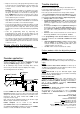
The decoder receives the digital information via the clamp
KL2. Connect the clamp with a rail or even better connect the
clamp directly to the command station or to a booster assuring
supply of digital information free from any interference.
Pay attention to the mark at clamp KL2. The color markings
'Black/Schwarz' and 'Red/Rot' next to the clamp are used for
Arnold-Digital (old) and Märklin-Digital= .
Other systems are using the letters 'J' and 'K'.
If you use the decoder for a Märklin-Digital~ respectively
Märklin-Motorola installation please attend to the colors marks
'red/rot' and 'brown/braun'.
The decoder receives the power supply via clamp KL1.
Voltage in the range of 14 to 18V~ is acceptable (alternate
current output of a model railway transformer).
If you do not want to supply power to the decoder SA-DEC-4
from an external transformer you can connect the clamp KL1
to KL2 with two wires. In this case the decoder will get the
power supply complete from the digital system.
Now connect the consumers (e.g. illumination, motors or
turnout- and signal coils) to the outputs 1 to 4. The contact
marked 'COM' is the common connection for the bistable relay.
Programming the decoder address:
For programming the decoder address you have to connect a
consumer to the output 1. As it is possible to hear the switching
of the bistable relay the connection of a consumer is not
mandatory.
Relais
REL3
Relais
REL2
D2
D3
C3
C5
C4
C7
CR1
R2
R1
ULN2803
IC3
Relais
REL1
KL6
B80C1500
GL1
R6
D1
CNY17
IC5
Z86E0...
IC1
D4
93C46
IC4
R9
R5
C6
KL5
R7
R4
R3
Relais
REL4
KL4KL3
KL1
Rev. 2.2
Littfinski DatenTechnik (LDT)
S1
KL2
Accessory Decoder
4fach Schaltdecoder
SA-DEC-4
COMCOM
COM COM
red brown
Black Red
1 2
3 4
K J
14..18V~
• Switch on the power supply of your model rail way.
• Depress the programming key S1. Do not touch the
integrated circuits of the pc-board because any electrostatic
discharge can destroy the IC`s.
• The relay connected to output 1 will now switch
automatically every 1,5 seconds. This indicates that the
decoder is in the programming mode.