
User manual

• Switch now one turnout of the group of four assigned to
the decoder via the keyboard of the control unit or via a
remote control. For programming the decoder address you
can also release a turnout switch signal via a personal
computer.
Remarks: The decoder addresses for magnet accessories
are combined in groups of four. The address 1 to 4 build
the first group. The address 5 to 8 build the second group
etc. Each S-DEC-4 decoder can be assigned to any of these
groups. Which turnout of a group will be activated for the
addressing does not matter.
• If the decoder has recognized the assignment correctly the
connected turnout will move a little faster. Afterwards the
movement slows down to the initial 1,5 seconds again.
In case the decoder will not recognize the address it could
be that the two digital information connections (clamp1) are
wrong connected. For testing this, switch the power supply
off, exchange the connection on KL1 and start addressing
again.
• Leave the programming mode by pressing the programming
key S1 again. The decoder address is now permanently
stored but it can be changed at any time by repeating the
programming as described above.
• If you press the first key of the programmed group of keys or
you send a switch signal for this turnout from a PC the
addressed turnout should move into the called direction
either into round or into straight. In case the movement goes
the wrong way please exchange the two turnout connection
cables at the ‚G‘reen (straight) and ‚R‘ed (round) marked
connection clamps of the decoder output 1.
Please attend to the following:
• All 4 decoder outputs can switch a current of 1 Ampere
peak. Modern turnout drives need about 0,25 up to 0,5
Ampere. Older drives which are not free moving or which
are dirty need more Ampere. The S-DEC-4 Decoder is
protected against overload caused by drives which are
not switching off at the end movement. The protector is an
automatic fuse which will switch back into normal operation
a few seconds after the load current is below maximum
value.
• Turnouts with integrated end-switch can create
considerable electromagnetic interference. Normally the
decoder S-DEC-4 will not be influenced by this interference.
In case the decoder will be influenced please check the
turnout installation cables. Those cables should not wrap
or cross the decoder closely. Install the cables that way that
they go straight away from the clamps of the decoder. If
limited space requires a bad installation layout and the
function of the decoder will be disturbed please disconnect
the middle cable of each turnout connection and push about
5 to 10 ferrous pearls onto this cable before connecting to
the clamp again.
• These ferrous pearls are available at electronic shops or at
LDT with the order code `FP`.
• Turnout illumination: If you want to have a realistic
switching of the turnout lights you can use the LDT
permanent power switch unit [DSU] or our switch
decoder SA-DEC-4.
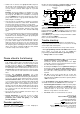
Decoder application:
The below draft provides examples of the multipurpose
application of the decoder S-DEC-4.
Besides the typical application of turnout control the decoder
can also be used for uncoupling tracks and signals.
12..18V~
1
2
3
4
S-DEC-4
Com R
G
DSU
Rev. 3.0
Littfinski DatenTechnik
KL2
KL1
KL3
Relais
turnouts
transformer
uncoupler
signals
lights
from
transformer
permanent power switch unit (DSU)
for lights or other consumers up to 2x 2A
With our permanent power switch unit [DSU], which is
equipped with a bi-stable relay is it possible to switch lights or
other consumers up to 4A digital on or off.
Further application and circuit examples can be found in the
Internet on our Web-Site (www.ldt-infocenter.com) at the
section downloads.
Under LDT-01 you can purchase a low priced durable suitable
case for the decoder S-DEC-4.
Please consult our Web-Site for further details.
Trouble shooting:
What to do if something is not working as described above?
If you have purchased the decoder as a kit please carefully
check all parts and soldered joints.
Here some possible functional errors and possible solutions:
1. During programming of the decoder addresses the turnout
moves within 1,5 seconds, but does not confirm the
programming with faster movement by pressing any key.
• Change cable connections at KL1.
• Interfered digital information at KL1 respectively lost of
voltage at the tracks or at the installation!
Connect the decoder directly with cables to the digital
control unit or to the booster instead to the tracks. Increase
the cable diameter for long distances.
• Eventually the clamps have been tightened to strong and
therefore the clamps got loose at the soldering to the pc
board. Check the soldering connection of the clamps at
the lower side of the pc-board and re-solder them if
required.
• For kits: Is IC5 correct inserted into the socket? Has
resistor R6 actually 220 kOhm or has this resistor been
mixed-up with the 18kOhm resistor R5 respectively with the
1MOhm resistor R7?
2. The programming of the decoder address functions as
described, nevertheless the turnouts will not be activated.
• Interfered digital information on KL1 respectively larger
lost of voltage at the tracks or the installation result to
unsafe data transfer! Connect the decoder directly to the
command station or the booster. Increase the cable
diameter of long distance connection cables.
• For the kit: Is IC4 correct inserted into the socket?
Made in Europe by
Littfinski DatenTechnik (LDT)
Kleiner Ring 9
D-25492 Heist/Germany
Phone: 0049 4122 / 977 381
Fax: 0049 4122 / 977 382
Internet: http://www.ldt-infocenter.com
Subject to technical changes and errors. 03/2014 by LDT
Arnold, Digitrax, Lenz, Märklin, Motorola, Roco and Zimo are
registered trade marks.