
User manual
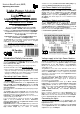

Picture 1: The Light-Power-Module has to get a direct current
supply of between 12 and 24 Volt. Each of the 24 outputs can
cover a maximum load of 2,5 Ampere.
Picture 2: Switched mode mains power supply are especially
suitable for the supply to the Light-Power-Modules because of the
possibility to supply a higher current level. Switched mode mains
power supply can be purchased by Conrad- (www.conrad.com)
and Reichelt Electronic (www.reichelt.de).
Computer
LPT-Schnittstelle
(Interface)
12...24V DC
max. 2,5 A max. 2,5 A
- +
Light Interface (LPT)
Rev. 1.0
Littfinski DatenTechnik (LDT)
BU1
IC2
IC3
IC4
BU2
IC1
C2
C1
Printer
Port
LPT
BU1
Light-Power
Rev. 1.2
Littfinski DatenTechnik (LDT)
12 ... 24 V DC
KL8
ST1
white weiss
white weiss
17
18
19
20
21
22
23
24
KL9 KL10 KL11
KL1 KL2 KL3 KL4 KL5 KL6 KL7
16
15
14
13
12
11
10
9
8
7
6
5
4
3
2
1
KL12
BU2
IN
BU3
OUT
-
+
L N
-V +V
V ADJ
(AC)
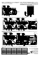
Picture 3: Attend to the correct polarity of the DC-current supply at the Light-Power-Modules.
- +
max. 2,5 Amax. 2,5 A
12...24V DC
- +
max. 2,5 Amax. 2,5 A
12...24V DC
Computer
LAN-Schnittstelle
(Interface)
Trxcom
Littfinski DatenTechnik (LDT)
DMX
KL5
BU2
PC/
LAN
Light-LAN (Ethernet Interface)
Rev. 1.0
Taster
BU1
ST1
KL1 KL2 KL3 KL4
+5V
GND
1
2
3
4
5
6
7
8
IC8
C4
C1
C2
L1
C3
Q1
CR1
C20
C19
C18
C17
C14
C12
C13C16
C15
RN1
RN2
IC3
IC1
IC2
C10
C21
C11
IC6
IC5
IC7
D1
C6
C5
C8
C9
BU1
Light-Power
Rev. 1.2
Littfinski DatenTechnik (LDT)
12 ... 24 V DC
KL8
ST1
white weiss
white weiss
17
18
19
20
21
22
23
24
KL9 KL10 KL11
KL1 KL2 KL3 KL4 KL5 KL6 KL7
16
15
14
13
12
11
10
9
8
7
6
5
4
3
2
1
KL12
BU2
IN
BU3
OUT
BU1
Light-Power
Rev. 1.2
Littfinski DatenTechnik (LDT)
12 ... 24 V DC
KL8
ST1
white weiss
white weiss
17
18
19
20
21
22
23
24
KL9 KL10 KL11
KL1 KL2 KL3 KL4 KL5 KL6 KL7
16
15
14
13
12
11
10
9
8
7
6
5
4
3
2
1
KL12
BU2
IN
BU3
OUT
Picture 4: The Layout-Light-Control Light-DEC consists of one Light-DEC-Basic and of up to 7 Light-Modules. Mixed usage of
Light-Display- (right) and Light-Power-Modules (left) is possible.
braun
brown
gelb
yellow
Vom Modellbahntrafo
From transformer
max. 1 Ampere
max. 0,5 Ampere
12...24V DC
max. 2,5 A max. 2,5 A
- +
BU1
Littfinski DatenTechnik (LDT)
Taster / Button
+5V
GND
1
2
3
4
5
6
7
8
IC5
D1
red brown
KL5
K J
KL1 KL2 KL3 KL4
Light-DEC-Service
Rev. 1.0
Littfinski DatenTechnik (LDT)
S1
S2
S4
S3
R1
Light-DEC V1.0
12:15:00 T 300
Rev. 1.0
Light-DEC-Basis
J
braun
brown
K
rot
red
Optional:
Von DCC-Digitalzentrale
oder Booster
From DCC command station
or booster
BU1
Light-Power
Rev. 1.2
Littfinski DatenTechnik (LDT)
12 ... 24 V DC
KL8
ST1
white weiss
white weiss
17
18
19
20
21
22
23
24
KL9 KL10 KL11
KL1 KL2 KL3 KL4 KL5 KL6 KL7
16
15
14
13
12
11
10
9
8
7
6
5
4
3
2
1
KL12
BU2
IN
BU3
OUT
white
weiss
white
weiss
KL4 KL3 KL2
KL1
KL7
BU1
ST1
4
5
6
7
8
26
27
28
29
30
31
32
25
9
10
11
12
13
14
15
16
18
19
20
21
22
23
24
17
1
2
3
GBS-Display / Light-Display
Rev. 1.8
Littfinski DatenTechnik (LDT)
KL5
braun
gelb
10...18V~
12...24V=
KL6
BU2
39
38
37
36
35
34
33
40
BU3
OUT
IN
Colored sample connections are available at our Web-Site www.ldt-infocenter.com within the section “Sample Connections”.
Table 1:
Made in Europe by
Littfinski DatenTechnik (LDT)
Kleiner Ring 9
D-25492 Heist/Germany
Phone: 0049 4122 / 977 381
Fax: 0049 4122 / 977 382
Internet: http://www.ldt-infocenter.com
Subject to technical changes and errors.
06/2016 by LDT
current wire cross section
0,5 sq mm
wire cross section
0,75 sq mm
wire cross section
1,5 sq mm
wire cross section
2,5 sq mm
1 Ampere 7,0 meter 10,5 meter 21,0 meter 35 meter
2 Ampere 3,5 meter 5,3 meter 10,5 meter 17,5 meter
3,5 Ampere 2,0 meter 3,0 meter 6,0 meter 10,0 meter
4 Ampere 1,8 meter 2,6 meter 5,3 meter 8,8 meter
5 Ampere 1,4 meter 2,1 meter 4,2 meter 7,0 meter