
User manual

Littfinski DatenTechnik (LDT)
Operating Instruction
Light-Power-Module
for the
Light Control
Light@Night and Light-DEC
Light-Power-F Part-No.: 050062
>> finished module <<
At least one Light-Power-Module and one Light-
Interface (LI-LPT or LI-LAN), will build together the
hardware of the PC-Layout-Light-Control Light@Night.
If a Light-Power-Module will be connected to a Light-DEC-
Basic-Module it will be the basic unit for the Layout Light
Control Light-DEC.
Light-Power-Modules contain 24 light outputs with a
max. current-load of 2.5 Ampere each.
The light effects (e.g. neon lamps, emergency flash lights, light
chains, traffic lights and many others) can be assigned
individually to each of the 24 outputs.
Suitable for analog and digital model railways.
This product is not a toy! Not suitable for children under 14 years of age! The kit
contains small parts, which should be kept away from children under 3! Improper
use will imply danger of injuring due to sharp edges and tips! Please store this
instruction carefully.
CE Part-No.:
146 40 20
Introduction/Safety instruction:
You have purchased the Light-Power-Module for the Light-
Control Light@Night and Light-DEC of the assortment of
Littfinski DatenTechnik (LDT).
We are wishing you having a good time using this product.
The finished module comes with 24 month warranty.
• Please read the following instructions carefully. Warranty will
expire due to damages caused by disregarding the operating
instructions. LDT will also not be liable for any consequential
damages caused by improper use or installation.
Connecting Light-Power-Module:
• Attention: Before starting the installation switch off the
drive voltage by pushing the stop button or disconnect
the main supply.
Connect the Light-Power-Module to the Light-Interface (LI-
LPT or LI-LAN), to the Light-DEC-Basic-Module or to already
available Light-Power- or Light-Display-Modules via the 10-
poles pin-plug-bar.
Take care that there is no offset between pin-bar plug and pin-
bar socket.
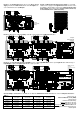
The modules are correct connected if the pc-board will be
flush at top and bottom. The picture 1 at the rear side of this
instruction shows the correct connection of the modules.
Light-Power- and Light-Display-Module do not need to be
connected directly to each other.
It is as well possible to connect the module via the „Kabel
L@N“ or via the screened and therefore interference
protected „Kabel Patch“ (from Light-Power Version 1.2 and
Light-Display Version 1.7).
Light-Power-Modules contain 24 outputs with a possible max.
current load of 2.5 Ampere each. With reason to the possible
high current output they are suitable for switching
simultaneous many incandescent model railway lamps e.g.
switching simultaneously light poles of one street.
Light-Power-Module and Light@Night:
The PC-Layout-Light-Control Light@Night consists of one
Light-Interface (LI-LPT or LI-LAN) and from the PC-Software
Version 2.0 of up to 7 Light-Modules with max. 280 light
outputs. A mixed application of Light-Power- and Light-
Display-Modules is possible. Light-Display-Modules contain
40 outputs each. Each output can cover a maximum load of
0.5 Ampere.
Light-Power-Module and Light-DEC:
Via one Light-DEC-Basic-Module can be up to 160 light
control outputs with max. 7 Light-Modules controlled.
Therefore is it possible to combine any desired Light-Power-
and Light-Display-Module. Light-Display-Modules provide 40
outputs with a possible current load of 0.5 Ampere.
If there are more than 160 light outputs required is it possible
to install further Light-DEC-Systems.
Voltage supply to the Light-Power-Modules:
The Light-Power-Modules have to be supplied with 12 to 24
Volt DC. The positive pole of the direct current voltage has
to be connected to one of the positive clamps of the Light-
Power-Module. As the four clamps of the Light-Power-
Module are connected to each other is it unimportant which
clamp will be used.
The picture 1 at rear side of this instruction shows how to
connect the negative pole of the direct current to all clamps
which are marked with “-“. This is required to prevent the
destruction of the printed circuit at the Light-Power-Module
during high current load.
The used voltage level of the direct current depends to the
incandescent model lamps which shall be connected to
Light-Power-Module. The voltage layout of incandescent
model lamps is mostly 16 Volt.
Feed the Light-Power-Module either by a direct current
transformer or even better by a switched mode mains power
supply (picture 2) which is able to supply a considerable
higher current output. Suitable switched mode mains power
supply e.g. with 15 Volt can be purchased by
Conrad (www.conrad.com) and Reichelt Electronic
(www.reichelt.de).
Please consider to implement a sufficient dimension of the
wires in correspondence to the required current load. The
table 1 at the rear side of this instruction shows the correlation
between current load, wire cross section and cable length.
Connecting the lights:
The common pole for all lamps is the positive pole. This
connection is available within the four positive clamps of the
Light-Power-Module.
All consumers will be switched to negative via the 24 outputs
of the Light-Power-Module. The maximum current at each
output can be up to 2.5 Ampere.
OUT
IN