
User manual

Littfinski DatenTechnik (LDT)
Assembly Instruction
Light-Power-Module
for the
Light Control
Light@Night and Light-DEC
Light-Power Part-No.: 050061
>> kit <<
At least one Light-Power-Module and one Light-Interface
(LI-LPT or LI-LAN) will build together the hardware of the
PC-Layout Light Control Light@Night.
If a Light-Power-Module will be connected to a Light-DEC-
Basic-Module it will be the basic unit for the Layout Light
Control Light-DEC.
Light-Power-Modules contain 24 light outputs with a max.
current load of 2.5 Ampere each.
The lighting effects (neon lamps, flashing blue light, light
chains, traffic lights and many others) can be assigned
individually to each of the 24 outputs.
Suitable for analog and digital model railways.
This product is not a toy! Not suitable for children under 14 years of age! The kit
contains small parts, which should be kept away from children under 3! Improper
use will imply danger of injuring due to sharp edges and tips! Please store this
instruction carefully.
CE Part-No.:
146 40 21
Introduction:
You have purchased a kit for your model railway that is
supplied within the assortment of Littfinski DatenTechnik
(LDT).
• These kits are easy to assemble and they are a product of
high quality.
• Model railway kits are not only welcome handicraft jobs but
they can be purchased with a considerable price reduction.
This will justify to spent about an hour because you do not
need more time to assemble those kits.
We are wishing you having a good time using this product.
General:
Tools required for the assembly
Please assure that the following tools are available:
• a small side cutter
• a mini soldering iron with a small tip
• solder tin (if possible 0,5mm diameter)
Safety Instructions
• All electrical and electronic components included in this kit
shall be used on low voltage only by using a tested and
approved voltage transducer (transformer). All components
are sensitive to heat. During soldering the heat shall be
applied for a very short period only.
• The soldering iron develops up to 400°C. Please keep
continual attention to this tool. Keep sufficient distance to
combustible material. Use a heat resistant pad for this work.
• This kit consists of small parts, which can be possibly
swallowed from children. Children (especially under 3 years)
should not participate on the assembly without supervision.
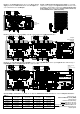
Set-Up:
For the board-assembly please follow exact the sequence of
the below assembly list. Cross each line off as done after
completing the insertion and the soldering of the respective
part.
For the diode please keep special attention to the correct
polarity (marked line for the cathode).
Attend to the connection marked “+” at the tantalum
capacitor. This mark has to correspond to the mark on the pc
board.
Resistor networks are marked for assembly with a printed
circle or a square at one end. Insert this component that way
that the marking correspond with the first and second bore of
the pc board. The first bore has been additionally marked at
the pc board with a “1”.
You can identify the 1kOhm network by the printed mark of
102 and the 100kOhm network by the printed mark 104.
Please assemble the clamps to blocks of 15 and 21
connections.
The transistors have to be assembled in that direction that the
metal side will face to the bold white line on the pc-board.
Integrated circuits (IC`s) are either marked with a half round
notch on one end or a printed point for the correct mounting
position. Push the IC`s into the correct socket assuring that the
notch or the printed point is corresponding to the half-rounded
marking on the pc-board.
Please attend to the sensitivity of the ICs to electrostatic
discharge which will cause immediate damage of the IC.
Before touching those components please discharge yourself
by contacting an earthed metal (for example: an earthed
radiator) or work with an electrostatic safety pad.
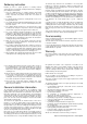
Cut out the labels for the sockets BU2 and BU3 and stick
them onto the RJ-45 sockets. This will indicate an explicit
identification for the connection of light power module via
patch cable.
OUT
IN
Label for BU3
Label for BU2
Assembly List:
Pos.
Qty.
Component
Remarks
Ref.
Done
1 1 Pc-board
2 1 Diode 1N4003 attend to polarity! D1
3 3 IC-Socket 16poles IC1...3
4 3 Capacitors 100nF 100nF = 104 C1...3
5 1 Tantalum cap. 10µF/10V attend to polarity! C4
6 6 Networks 4*1kOhm attend to polarity! (102) RN1...6
7 6 Networks 4*100kOhm attend to polarity! (104) RN7...12
8 1 Socket bar 10poles BU1
9 1 Pin bar 10poles ST1
10 2 RJ45 Sockets BU2, BU3
11 12 Clamps 3poles build blocks before assy.! KL1...12
12 24 Transistor BUZ11 attend to polarity! T1...24
13 3 IC: 4094 attend to polarity! IC1...3
14 Final Control
Made in Europe by
Littfinski DatenTechnik (LDT)
Kleiner Ring 9
D-25492 Heist/Germany
Phone: 0049 4122 / 977 381
Fax: 0049 4122 / 977 382
Internet: http://www.ldt-infocenter.com
Subject to technical changes and errors. 06/2016 by LDT