
User manual

Littfinski DatenTechnik (LDT)
Operating Instruction
Light-Display-Module
for the
Light Control
Light@Night and Light-DEC
Light-Display-F Part-No.: 050032
>> finished module <<
At least one Light-Display-Module and one Light-Interface
(LI-LPT or LI-LAN) will build together the hardware for the PC-
Layout-Light Control Light@Night.
The connection of a Light-Display-Module to a Light-DEC-
Basis-Module will create the basic unit for the
Layout Light Control Light-DEC.
Light-Display-Modules contain 40 light outputs with a
possible current load of 0.5 Ampere on each output.
The lighting effects (neon lamps, flashing blue light, light
chains, traffic lights and many others) can be assigned to 40
outputs.
Suitable for analog and digital model railways.
This product is not a toy! Not suitable for children under 14 years of age! The kit
contains small parts, which should be kept away from children under 3! Improper
use will imply danger of injuring due to sharp edges and tips! Please store this
instruction carefully.
CE Part-No.:
146 40 18
Introduction/Safety instruction:
You have purchased the Light-Display-Module for the Light
Control Light@Night and Light-DEC for your model railway.
The Light-Display-Module is a high quality product that is
supplied within the assortment of Littfinski DatenTechnik (LDT).
We are wishing you having a good time using this product.
The finished module comes with 24 month warranty.
• Please read the following instructions carefully. Warranty will
expire due to damages caused by disregarding the operating
instructions. LDT will also not be liable for any consequential
damages caused by improper use or installation.
Connect the Light-Display-Module:
• Attention: Before starting the installation switch off the
drive voltage by pushing the stop button or disconnect
the main supply.
• The Light-Display-Modules contain a large capacitor
which has to be completely discharged before the Light-
Display-Module can be connected or disconnected.
Please wait a couple of minutes after switching off the
supply transformer before you connect or disconnect the
Light-Display-Module.
Connect the Light-Display-Module to the Light-Interface (LI-
LPT or LI-LAN), to the Light-DEC-Basic-Module or to the
already available Light-Power- or Light-Display-Modules via
the 10-poles pin-plug-bar.
The pin bar shall not be inserted in offset position to the
socket bar.
The modules are correct inserted whenever the pc-boards
are flash at the top and at the bottom. The pictures at the rear
side of this instruction show the correct position of the modules.
Light-Power- and Light-Display-Module do not need to be
connected directly to each other. It is as well possible to
connect the module via the “Kabel L@N” or via the screened
and therefore interference protected “Kabel Patch” (from
Light-Power Version 1.2 and Light-Display Version 1.7).
Light-Display-Modules contain 40 outputs with a maximum
load of 0.5 Ampere each. They are particular suitable for
switching light sources such as incandescent model railway
lamps or light emitting diodes (LED).
Voltage supply to the Display-Modules:
Each Light-Display-Module will get the voltage from a model
railway transformer via the clamp KL6.
The supply voltage can be between 10 and 18 Volt AC or
between 12 and 24 Volt DC.
If you use mainly light emitting diodes on your layout it is
possible that one 52VA transformer can supply more then
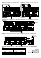
one Light-Display-Module. Picture 3 at the rear side of this
instruction shows how to arrange the supply of one
transformer to two Light–Display-Modules.
Please attend always to the same polarity (marked brown
and yellow) at the clamp KL6 of the connected Light-Display-
Module.
If you use incandescent lamps for illumination one 52VA
transformer can supply one Light-Display-Module. Also in
this case please attend always to the same polarity (marked
brown and yellow) at the clamp KL6 of the connected Light-
Display-Module (Picture 4 at the rear side of this instruction).
Connect the Illumination:
Each Light-Display-Module contains 40 outputs. Model
incandescent lamps can be directly connected. LED`s
require a serial resistor (about 4,7kOhm, depending to the
input voltage on KL6).
Each output can be loaded up to max. 0.5 Ampere. For
clamping a connection cable onto one of the 40 outputs please
press carefully down the white lever and insert the cable from
the top into the clamp.
If the Light-Display-Module will be supplied with AC-voltage is
the DC-voltage at the 40 outputs about (1,414 * input voltage)
– 1.4 Volt. An AC input voltage of e.g. 15 Volt (on KL6) will give
a DC-voltage of about 20 Volt at the outputs.
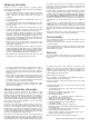
If the Light-Display will be supplied with DC voltage on KL6
the output DC voltage will be lower by about 1,4 Volt related
to the input voltage. The interrelation between input and output
voltage will be shown on table 1 at the rear side of this
instruction.
The common positive pole for all outputs is clamp KL7
(Picture 1 at the rear side).
The common positive pole contains three inputs which can
be loaded with 1 Ampere each. Distribute the common
positive connection of the lamps and LED`s evenly to the three
positive clamps KL7 (Picture 2 at the rear side).
OUT
IN