
User manual


Littfinski DatenTechnik (LDT)
Assembly Instruction
Light-DEC-Service Module
for Light-DEC
from the Digital-Professional-Series !
>> kit <<
The Light-DEC-Service Module can only be used
together with the Light-DEC-Basic Module.
The unit has to be connected and screwed to
the 20-poles socket bar of the basic module as
described within the assembly instruction of the
Light-DEC-Basic Module.
This product is not a toy! Not suitable for children under 14 years of age!
The kit contains small parts, which should be kept away from children under 3!
Improper use will imply danger of injuring due to sharp edges and tips! Please
store this instruction carefully.
Introduction:
You have purchased the Light-DEC-Service-Module for your
model railway that is supplied within the assortment of
Littfinski DatenTechnik (LDT).
• These kits are easy to assemble and they are a product of
high quality.
• Model railway kits are not only welcome handicraft jobs but
they can be purchased with a considerable price reduction.
This will justify to spend about an hour because you do not
need more time to assemble those kits.
We are wishing you having a good time using this product.
General:
Tools required for the assembly
Please assure that the following tools are available:
• a small side cutter
• a mini soldering iron with a small tip
• solder tin (if possible 0,5mm diameter)
Safety Instructions (attend as well to the rear side of this
instruction)
• All electrical and electronic components included in this kit
shall be used on low voltage only by using a tested and
approved voltage transducer (transformer). All components
are sensitive to heat. During soldering the heat shall be
applied for a very short period only.
• The soldering iron develops up to 450°C. Please keep
continual attention to this tool. Keep sufficient distance to
combustible material. Use a heat resistant pad for this work.
• This kit consist of small parts, which can be possibly
swallowed from children. Children (especially under 3 years)
should not participate on the assembly without supervision.
Set-Up:
For the board-assembly please follow exact the sequence of
the below assembly list. Cross each line off as done after
completing the insertion and the soldering of the respective
part.
For the diodes please keep special attention to the correct
polarity (marked line for the cathode).
Before assemble the Display is it required to assemble and
solder correctly the two 10-poles and the 14-poles pin-bars
onto the Light-DEC-Service pc-board. Correct assembly of the
two pin-bars will be if the shorter side with the shorter pins will
be inserted into the pc-board.
It is essential that the two 10-poles pin-bar will be inserted
that the soldering will be performed from the printed
assembly side of the board.
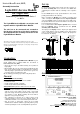
Then plug-on the display onto the 14-poles pin plug bar and
secure it with distance spacers, Phillips-screws and hexagon
nuts as shown below. Now shall the 14-poles pin plug bar to
be soldered to the display.
Leiterplatte mit Stiftleisten
PCB with pin headers
Sechskantmutter
hexagonal nut
Distanzhülse
distance spacer
Display
display
Schraube
screw
Leiterplatte mit Stiftleisten
PCB with pin headers
Sechskantmutter
hexagonal nut
Distanzhülse
distance spacer
Display
display
Schraube
screw
Assembly List:
Pos.
Qty.
Component
Remarks
Ref.
Done
1 1 Pc-board
2 5 Diode 1N4148 attent to the polarity! D1...D5
3 4 Push button S1...S4
4 1 Trim-pot 10kOhm P1
5 1 Pin plug bar 2x10poles attend to direction! ST1
6 1 Pin plug bar 14poles ST2
7 4 Distance spacer 5mm for assembly of display
8 4 Phillips screw M 2,5 for assembly of display
9 4 Hexagon nut M 2,5 for assembly of display
10 1 Display (Point-Matrix) display
11 final control
Assembly Plan:
Made in Europe by
Littfinski DatenTechnik (LDT)
Kleiner Ring 9
D-25492 Heist/Germany
Phone: 0049 4122 / 977 381
Fax: 0049 4122 / 977 382
Internet: http://www.ldt-infocenter.com
Subject to technical changes and errors. 04/2016 by LDT