
Instructions

Switching turnouts via loc-addresses
(e.g. Lokmaus 2® or R3®):
The decoder M-DEC-DC makes it possible to switch motor
driven turnouts via loc-addresses. For example switching with
the functional keys F1 to F4 of the Lokmaus 2® or R3®.
The function key F1 will shift the drive at the output 1 and the
key F2 will shift the turnout at the output 2 etc.
Each stroke on a function key will shift the respective
turnout from round to straight or vice versa.
Also for programming the loc-addresses a turnout motor-drive
has to be connected to the output 1 of the decoder.
• Switch the power supply of your model rail way on.
• Adjust the speed of all connected speed controller
respectively Lokmauses to zero (center position of the
adjusting dial).
• Press the programming key S1.
• The motor drive connected to output 1 shall move now
automatically every 1,5 seconds. This indicates that the
decoder is in the programming mode.
• Adjust now on one of the Lokmauses the required address
and turn the speed adjusting dial off from the center
position. If the decoder has recognized the assignment
correctly the connected turnout drive will move now a little
faster. The decoder M-DEC-DC will accept loc-addresses
between 1 and 99.
• Adjust the speed now to zero again. The turnout will move
now a little slower.
• Press the programming key S1 again for leaving the
programming mode.
• If you press functional key F1 you can shift the turnout of
the output 1 with each stroke. If there are turnouts
connected on output 2 to 4 of the decoder M-DEC-DC you
can shift the respective registered turnouts with the
programmed loc-addresses with each stroke of the function
keys F2 to F4.
Please attend to the following:
• All 4 decoder outputs can supply a motor current of 1
Ampere. As the moving time of the drives is only some
seconds the tracking time of the decoder output is adjusted
to 10 seconds. This indicates that the respective output will
be switched voltage free 10 seconds after the end of the
switch command. This assures that a defect end-switch
will not destroy a drive with continuous current.
• The motors of turnout drives can create considerable
electromagnetic interference. Normally the decoder M-
DEC will not be influenced by this interference. But in case
the decoder will be influenced please check the turnout
drive installation cables. Those cables should not wrap or
cross the decoder closely. Install the cables that way that
they go straight away from the clamps of the decoder. If
limited space requires a bad installation layout and the
function of the decoder will be disturbed please push about
5 ferrous pearls onto each motor cable.
These ferrous pearls are available at electronic shops or at
LDT with the order code `FP`.
Another possibility is to solder an interference capacitor
(between 1nF and 10nF) across each motor. Fulgurex
drives need this capacitor in any case.
Accessory
For the assembly of the M-DEC below your layout base plate is
our assembly set MON-Set recommended. For the ready
assembled kits and the finished modules from version 2.0 we
offer a suitable case under the order code LDT-01.
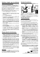
Sample Connections:
Spannungsversorgung
12 ... 18V~
15 ... 24V=
3
4
1
2
Fulgurex
Pilz/Tillig
M-DEC
Digitalinformationen
(von Steuereinheit oder Booster)
Hoffmann
Conrad
The above draft provides an example how to connect the
different drives directly to the M-DEC-DC without any additional
circuitry.
Further application examples can be found in the Internet on
our Web-Site (www.ldt-infocenter.com) at the section
downloads/sample connections.
Trouble shooting:
What to do if something is not working as described above?
If you have purchased the decoder as a kit please check
carefully all parts and soldered joints.
Here some possible functional errors and possible solutions:
1. During programming of the decoder addresses the motor
moves within 1,5 seconds, but does not confirm the
programming with faster movement by pressing any key.
• Interfered digital information at KL2 respectively
considerable lost of voltage at the tracks or at the
installation! Connect the decoder directly with cables to
the digital control unit or to the booster instead to the
tracks.
• Eventually the clamps have been tightened to strong and
therefore the clamps got loose at the soldering to the pc
board. Check the soldering connection of the clamps at
the lower side of the pc-board and re-solder them if
required.
• For kits: Is IC4 and IC5 correct inserted into the socket?
Has resistor R6 actually 220kOhm or has this resistor been
mixed-up with the 18kOhm resistor R5?
2. The turnout connected to output 1 will move always at a
faster sequence after activating the programming key S1.
• Start programming the decoder for motor driven turnouts
M-DEC-DC immediately after switching-on the digital
central unit before any loc is traveling on the track.
• Perform a RESET of the digital central unit. All stored data
will be preserved but the address-repeating-memory will
be deleted. For Intellibox and TWIN-CENTER please
switch-on the unit and press the keys GO and STOP
simultaneous until the report “reset” can be red at the
display.
3. The drive moves not until the end switch but stops after a
short movement. The decoder does not show any reaction
after some commands.
• This can happen especially by Fulgurex-drives without
interference capacitor. Solving: solder an interference
capacitor (1nF) directly to the motor connection clamps.
Made in Europe by
Littfinski DatenTechnik (LDT)
Kleiner Ring 9
D-25492 Heist/Germany
Phone: 0049 4122 / 977 381
Fax: 0049 4122 / 977 382
Internet: http://www.ldt-infocenter.com
Subject to technical changes and errors. 06/2014 by LDT
Arnold, Märklin, Lenz, Digitrax, Roco and Zimo are registered trade marks.