
User manual
Littfinski DatenTechnik (LDT)
Assem
bly Instruction
Reverse-Loop Module
from the Digital-Professional-Series !
KSM-SG-B Part-No.: 700501
>> kit <<
Suitable for the digital operation of all digital
formats
The polar reversal at the reverse-loop will be performed
without short-circuit via two sensor rails.
With reason to an external power supply possibility is a
simple control of the reverse-loop with track occupancy
module (e.g. RM-GB-8(-N) and RS-8) possible. The sensor
rails will be controlled as well.
This product is not a toy! Not suitable for children under 14 years of age!
The kit contains small parts, which should be kept away from children under 3!
Improper use will imply danger of injuring due to sharp edges and tips! Please
store this instruction carefully.
CE Part-No.:
24 80 35
Introduction:
You have purchased a kit for your model railway supplied within
the assortment of Littfinski DatenTechnik (LDT).
This kits are a high quality product which is easy to assemble.
We are wishing you having a good time for assembling and
application of this product.
General:
Tools required for the assembly
Please assure that the following tools are available:
• a small side cutter
• a mini soldering iron with a small tip
• solder tin (if possible 0,5mm diameter)
Safety Instructions
• All electrical and electronic components included in this kit
shall be used on low voltage only by using a tested and
approved voltage transducer (transformer). All components
are sensitive to heat. During soldering the heat shall be
applied for a very short period only.
• The soldering iron develops a heat up to 400°C. Please keep
continual attention to this tool. Keep sufficient distance to
combustible material. Use a heat resistant pad for this work.
• This kit consist of small parts which can possibly be
swallowed from children. Children (especially under 3 years)
shall not participate on the assembly without supervision.
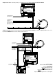
Set-Up:
For the board-assembly please follow exact the sequence of the
below assembly list. Cross each line off as done after
completing the insertion and the soldering of the respective
part.
For the diodes and zener diodes please keep special attention
to the correct polarity (marked line for the cathode).
With reason to different makes of electrolytic capacitors you
will find different markings of the polarity. Some are marked with
"+" and some are marked with "-". Each capacitor has to be
assembled to the board that the marking on the capacitor is in
correspondence with the marking on the pc-board.
Integrated circuits (IC`s) are either marked with a half round
notch on one end or a printed point for the correct mounting
position. Push the IC`s into the correct socket or directly into the
pc-board (IC3) assuring that the notch or the printed point is
corresponding to the half-rounded marking on the pc-board.
Please attend to the sensitivity of the IC`s to electrostatic
discharge which will cause immediate damage of the IC.
Before touching those components please discharge yourself
by contacting an earthed metal (for example an earthed
radiator) or work with an electrostatic safety pad.
Please attend to the mark "+" of the rectifiers. Some
manufacturers mark the "+" connections additionally with a
longer connection wire. If the rectifier shows as marking a
flattened side this side has to correspond with the marking on
the pc-board.
The clamps KL1 to KL4 have to be connected to a block with 8
connections.
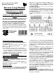
Assembly List:
Pos.
Qty.
Component
Remarks
Ref.
Done
1 1 Printed circuit board
2 1 Z-Diode BZX ... 5V1 attend to the polarity! D1
3 5 Diodes 1N4003 attend to the polarity! D2, D6
4 1 Z-Diode BZX ... 30 attend to the polarity! D7
5 1 Resistor 820Ohm gray-red-black-black R1
6 2 Resistors 1,5kOhm brown-green-black-brown R2, R3
7 1 Resistor 220kOhm red-red-black-orange R4
8 1 Resistor 1MOhm brown-black-black-yellow R5
9 2 Capacitors 100nF 100nF = 104 C3, C4
10 2 IC-Sockets 18poles IC1, IC2
11 1 IC-Socket 8poles IC4
12 1 IC: 814 attend to the polarity! IC3
13 1 Resonator CR1
14 1 Electrolytic-cap. 100µF/25V attend to the polarity! C2
15 1 Electrolytic-cap. 470µF/35V attend to the polarity! C1
16 1 Rectifier attend to the polarity! GL1
17 1 Multi Fuse R050 MF1
18 3 Relay REL1..3
19 4 Clamps 2poles build blocks before assy. KL1, KL4
20 1 Clamp 2poles KL5
21 1 IC: Z86E0..PSG attend to the polarity! IC1
22 1 IC: ULN2803A attend to the polarity! IC2
23 1 IC: 93C46 attend to the polarity! IC4
Final control
Made in Europe by
Littfinski DatenTechnik (LDT)
Kleiner Ring 9
D-25492 Heist/Germany
Phone: 0049 4122 / 977 381
Fax: 0049 4122 / 977 382
Internet: http://www.ldt-infocenter.com
Subject to technical changes and errors. 05/2013 by LDT