
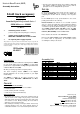
User manual

Littfinski DatenTechnik (LDT)
Assembly Instruction
8-fold track occupancy
detector
from the Digital-Professional-Series !
GBM-8-B Part-No.: 020001
>> kit <<
⇒ monitoring 8 track sections
(current sensing from 0,001[1mA] up to 3 Ampere)
⇒ suitable for the feedback modules
RM-88-N-O / RM-DEC-88-O and Roco 10787
⇒ no separate power supply required
This product is not a toy! Not suitable for children under 14 years of age! The kit
contains small parts, which should be kept away from children under 3! Improper
use will imply danger of injuring due to sharp edges and tips! Please store this
instruction carefully.
CE Part-No.:
40 43 97
Introduction:
You have purchased the 8-fold track occupancy detector GBM-8
for your model railway layout. The GBM-8 is a high quality
product that is supplied within the Digital-Professional-Series
of Littfinski DatenTechnik (LDT).
We wish you having a good time using this product.
The track occupancy detector GBM-8 of the Digital-
Professional-Series can be easily operated on your digital
model railway.
The GBM-8 is suitable for the direct connection to the
feedback modules RM-88-N-O / RM-DEC-88-O and Roco
10787.
General:
Tools required for the assembly
Please assure that the following tools are available:
• a small side cutter
• a mini soldering iron with a small tip
• solder tin (if possible 0,5mm diameter)
Safety Instructions
• All electrical and electronic components included in this kit
shall be used on low voltage only by using a tested and
approved voltage transducer (transformer). All components
are sensitive to heat. During soldering the heat shall be
applied for a very short period only.
• The soldering iron develops a heat up to 400°C. Please keep
continual attention to this tool. Keep sufficient distance to
combustible material. Use a heat resistant pad for this work.
• This kit consist small parts which can possibly be swallowed
from children. Children (especially under 3 years) shall not
participate on the assembly without supervision.
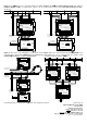
Set-Up:
For the board-assembly please follow exact the sequence of
the below assembly list. Cross each line off as done after
completing the insertion and the soldering of the respective
part.
For the diodes please keep special attention to the correct
polarity (marked line for the cathode).
Resistor-networks are marked on one end with a printed
circle or a square. Assemble this component that way that the
marking corresponds with the marking between the first and
second bore respectively with the marking “1” on the pc-board.
The 330Ohm networks (RN1 and RN2) contain the label
“331” for identification of the resistance value. The 10kOhm
networks (RN3 and RN4) contain the label “103”.
Please attend to the flat side of the transistors.
Please put the 2-pole clamps and the 3-pole clamps together
to a block with 10 respectively 12 connections before
assembling the clamps to the board.
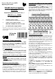
Assembly List:
Pos. Qty. Component Remark Ref. Done
1 1 Printed Circuit Board
2 10 Diode 1N4148 Attend to the polarity! D17...26
3 8 Resistor 1kOhm brown-black-black-brown R1...R8
4 8 Resistor 220kOhm red-red-black-orange R9...R16
5 2 Network 4*330Ohm Attend to the polarity! (331) RN1, 2
6 2 Network 4*10kOhm Attend to the polarity! (103) RN3, 4
7 8 Capacitor 22pF C1...C8
8 16 Diode BY251 Attend to the polarity! D1...D16
9 8 Transistor BC 547 T1...T8
10 6 Clamp 3-poles Build a block before assembly KL1...6
11 2 Clamp 2-poles Build a block before assembly KL7, 8
12 Final Control
Made in Europe by
Littfinski DatenTechnik (LDT)
Kleiner Ring 9
D-25492 Heist/Germany
Phone: 0049 4122 / 977 381
Fax: 0049 4122 / 977 382
Internet: http://www.ldt-infocenter.com
Subject to technical changes and errors. 05/2013 by LDT
Roco is a registered trademark.