
User manual

DigitalBooster DB-4 – Manual
- 7 -
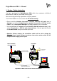
The digital current of the DigitalBooster DB-4 is available at the clamp KL1 next to
the two light emitting diodes.
The DB-4 supplies digital current to the own track section via this clamp. This
section has to be electrical separated from the adjoining track sections because
those receive their supply from the digital command station with integrated
booster or from further booster.
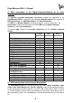
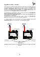
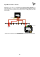
4.1. 3-Conductor Track System:
If the manufacturer of your digital command station permits a common layout ground
(“brown”) the center conductor of the 3-conductor track has to be isolated at the
cross over joints from one to the next booster electrical circuit. The isolated center
conductor gets the supply from the connection “red” of the clamp KL1 of the
DigitalBooster DB-4.
È
BU1
+
S1
DCCMM
JP1
JP2
JP3
JP4
OFFON
Auto Go
RailCom
ShortReport
red brown
LED1 LED2
GO STOP
+
Littfinski DatenTechnik (LDT)
KL1
K J
4,52,5
JP5
OUTIN
ST1 ST2
Rev. 1.4
DB-4
BU3
BU2
C D E
STOP/GO
KL2 KL4 KL3
Feedback
A
T
2,5 / 4,5 Ampere Booster für die Digitalformate Märklin-
Motorola, mfx
®
, M4 und DCC.
2,5 / 4,5 ampere booster for Märklin-Motorola, mfx
®
, M4
and DCC.
DB-4
DigitalBooster
Multi-Digital
L
ittfinski
D
aten
T
echnik (
LDT
)
D-25492 Heist
www.ldt-infocenter.com
Digital-Profi werden!
braun
brown
rot
red
Vom DB-4-Power-Supply
From DB-4-Power-Supply
rot
red
braun
brown
Von Digitalzentrale
oder Booster
From command station
or booster
J K J K
Booster separation by common layout ground with isolated center conductor
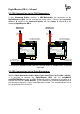
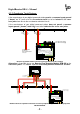
If the manufacturer of the digital command station does not permit a common layout
ground (“brown”) it is required additionally to isolate the rails at the cross over
joints.
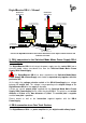
If the manufacturer of the digital command station stipulates mandatory the
installation of a rocker switch at the cross sections of the center conductor this
switch has to be installed.