
User manual

DigitalBooster DB-4 – Manual
- 13 -
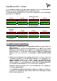
The following programming samples are indicating how to employ four-fold
address groups with 8 keys of a switch board.
The address has been indicated between the respective pair of keys.
The two keys red and green for each address are the two possible switch
directions of this address with reference to the turnout direction round and straight.
If you use a remote control LH100 of company Lenz Elektronik there will be red the
minus- and green the plus key.
round / red / - round / red / - round / red / - round / red / -
1 2 3 4
straight / green / + straight / green / + straight / green / + straight / green / +
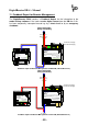
7.1. Common Address Section:
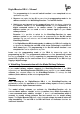
If there will be a common four-fold address block programmed for the WatchDog-
and the On-/Off switch function the DigitalBooster DB-4 will occupy 4 accessory-
or turnout addresses.
WatchDog On-/Off sw. Funktion
inactivated not used Stop not used
round / red / - round / red / - round / red / - round / red / -
1 2 3 4
straight / green / + straight / green / + straight / green / + straight / green / +
activated not used Go not used
WatchDog On-/Off sw. Function
With the above table has been the DigitalBooster DB-4 programmed for the
WatchDog- and the On-/Off switch function for a common address section of 1 to
4.
With the basic address 1 of the four-fold address block will be the WatchDog-
Function controlled. With the basic address + 2 and the address 3 as per sample
will be the On-/Off switch function controlled.
The addresses 2 and 4 will not be used.
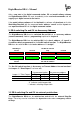
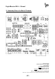
7.2. Own Address Sections:
If there will be own four-fold address groups programmed for the WatchDog- and
On-/Off switch function there will be 8 accessory- or turnout addresses assigned
by the DigitalBooster DB-4.