
User manual


Introduction:
You have purchased a kit for your model railway supplied within the assortment of
Littfinski DatenTechnik (LDT). These kits are of high quality and easy to assemble.
We are wishing you having a good time for assembling and application of this
product!
General:
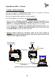
Tools required for the assembly
Please assure that the following tools are available:
• a small side cutter
• a mini soldering iron with a small tip
• solder tin (if possible 0,5mm diameter)
Safety Instructions
• All electrical and electronic components included in this kit shall be used on low
voltage only by using a tested and approved voltage transducer (transformer). All
components are sensitive to heat. During soldering the heat shall be applied for a
very short period only.
• The soldering iron develops a heat up to 400°C. Please keep continual attention to
this tool. Keep sufficient distance to combustible material. Use a heat resistant pad
for this work.
• This kit contains small parts which can possibly be swallowed from children.
Children (especially under 3 years) shall not participate on the assembly without
supervision.
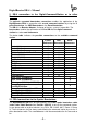
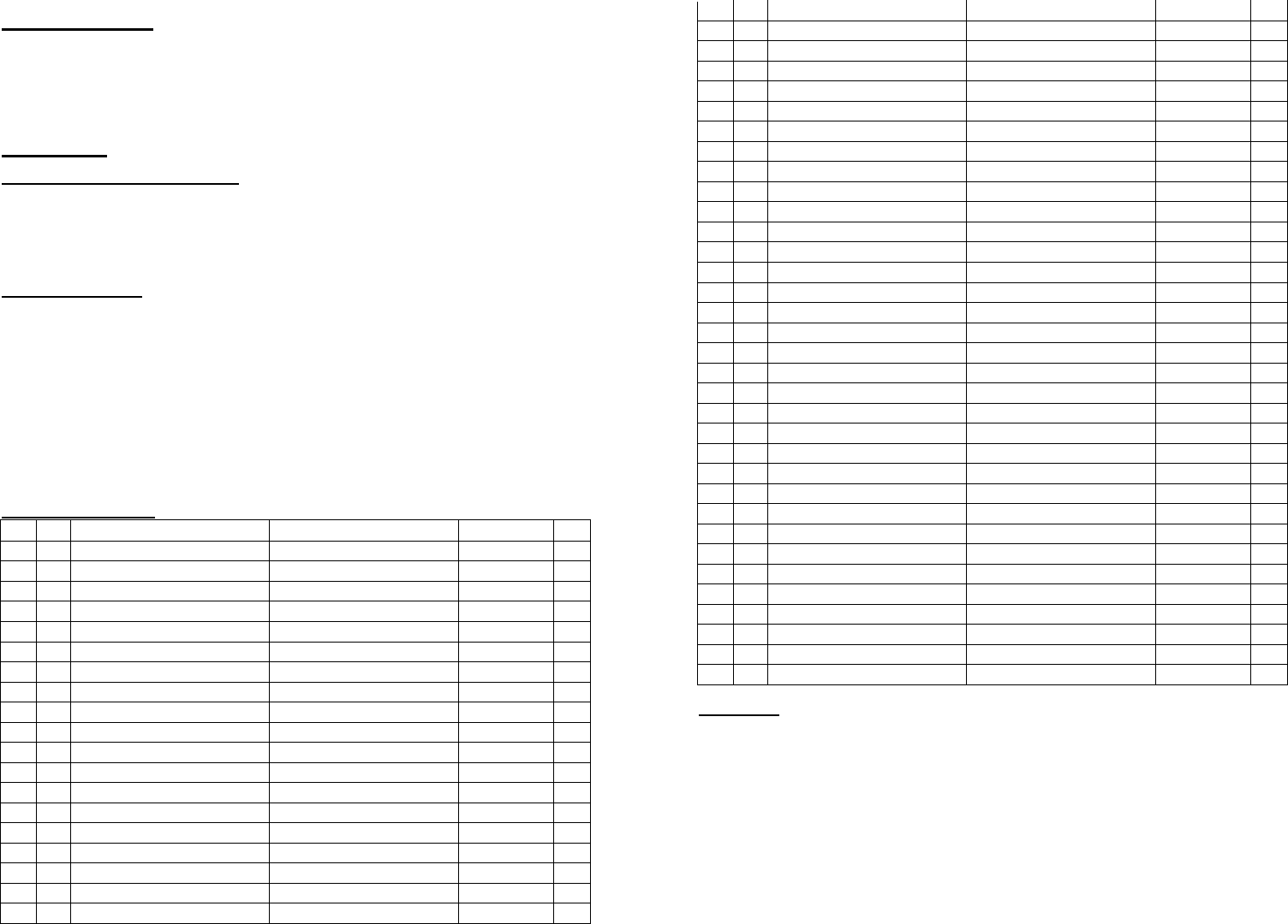
Assembly List:
Pos.
Qty.
Components Remarks Ref. Done
1 1 Printed circuit board DB-4 Rev. 1.4
2 2 Resistors 0,1 Ohm Marked: "R10" R1, R2
3 1 Resistor 10 Ohm brown-black-black-gold R3
4 1 Resistor 100 Ohm brown-black-black-black R4
5 1 Resistor 180 Ohm brown-gray-black-black R5
6 2 Resistors 220 Ohm red-red-black-black R6, R7
7 1 Resistor 330 Ohm orange-orange-black-black R8
8 1 Resistor 470 Ohm yellow-violet-black-black R9
9 1 Resistor 1 KOhm brown-black-black-brown R10
10 1 Resistor 2,2 KOhm red-red-black-brown R12
11 2 Resistors 3,3 KOhm orange-orange-black-brown R13, R14
12 2 Resistors 4,7 KOhm yellow-violet-black-brown R15, R16
13 4 Resistors 10 KOhm brown-black-black-red R11,R18...R20
14 1 Resistor 12 KOhm brown-red-black-red R21
15 1 Resistor 27 KOhm red-violet-black-red R22
16 3 Resistors 47 KOhm yellow-violet-black-red R17,R23,R24
17 1 Resistor 1 MOhm brown-black-black-yellow R25
18 1 Network 5*10 KOhm attend to polarity! RN1
19 10 Diodes 1N4003 attend to polarity! D1...4, D6...11
20 3 Diodes 1N5819 attend to polarity! D5, D12, D13
21 1 Z-Diode BZX ... 5V1 attend to polarity! D14
22 1 Z-Diode BZX ... 30V attend to polarity! D15
23 1 IC-socket 28poles attend to polarity marking! IC1
24 3 IC-sockets 8poles attend to polarity marking! IC2, 3, 5
25 1 IC-socket 16poles attend to polarity marking! IC7
26 1 IC: LTV814 attend to polarity! IC6
27 1 DC-DC Converter attend to polarity! IC4
28 1 Resonator 8MHz CR1
29 5 Capacitor 100nF 100nF = 104 C1...C5
30 1 Tantalum cap. 1uF/35V 1uF = 105; attend to polarity! C6
31 3 Tantalum cap. 10uF/10V 10uF = 106; attend to polarity! C7...C9
32 4 Electrolytic cap. 470uF/35V attend to polarity! C10...C13
33 1 Storage choke L1
34 1 DC-socket BU1
35 2 Sockets 4poles BU2, BU3
36 1 Socket bar 2x10poles BU4
37 1 Pin bar 2x5poles JP1 ... JP5
38 5 Jumpers set on pin bar 2x5poles JP1 ... JP5
39 2 Pin bars 5poles ST1, ST2
40 1 Push button S1
41 1 LED green plus distance sleeve attend to polarity! LED1
42 1 LED red plus distance sleeve attend to polarity! LED2
43 1 Clamp 2poles KL1
44 3 Clamps 2poles and 3poles build block prior to assembly KL2 ... KL4
45 1 IC: ATMEGA168-20 attend to polarity! IC1
46 1 IC: LM2574HVN-5 attend to polarity! IC2
47 1 IC: LM393 attend to polarity! IC3
48 1 IC: HCPL2631 attend to polarity! IC5
49 1 IC: LTV847 attend to polarity! IC7
50 4 Cross headed screws M3x6 for assembly "DB4-Power"
51 2 Distance spacer 18mm for assembly "DB4-Power"
52 1 DB4-Power assembly acc. instruction
53 final control
Set-Up:
For the board assembly please follow exact the sequence of the above assembly list.
Cross each line off as done after completing the insertion and the soldering of the
respective part.
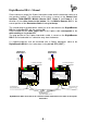
For the diodes please keep special attention the correct polarity (marked line for the
cathode).
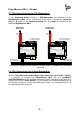
With reason to different makes of electrolytic capacitors you will find different
markings of the polarity. Some are marked with "+" and some are marked with "-".
Each capacitor has to be assembled to the board that the marking on the capacitor is
in correspondence with the marking on the pc-board.
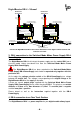
For tantalum capacitors please attend to the connection wire marked "+". This wire
has to correspond to the printed mark on the pc-board.