
User manual

DigitalBooster DB-4 – Manual
- 15 -
The programming for the on-/off switch function is now completed but can
repeated at any time.
3. Depress now again the key S1 to come into the programming mode for the
address section of the WatchDog-Function. The red LED flashes.
4. Switch now one turnout from the group of four which has been selected for
the address section of the WatchDog-Function via the keyboard of the
digital command station or the remote control. For programming the
address section you can send as well a turnout signal via your model
railway software.
Remarks: It is possible to select for the WatchDog-Function the same
address section as you used already for programming the On-/Off switch
function. But you can select as well an own four-fold address block for the
WatchDog-Function.
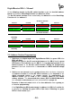
If the DigitalBooster DB-4 understands the address the DB-4 will confirm the
assignment by flashing the red LED a little faster. Following the red LED will
flash slower again. The programming for the On-/Off switch function is now
completed but can be repeated at any time.
Leave now the programming mode of the DB-4 by depressing again the
programming key S1. The programmed addresses are now permanently stored
but can be changed at any time by repeating the programming process. Now the
green LED will glow and the track section which is connected to the DB-4 will get
supply of digital voltage.
8. WatchDog: Communication with the Model Railway Software:
If your model railway software supports the WatchDog-Function of the DB-4
respectively our WatchDog-Decoder WD-DEC please register in your model railway
software your selected address for the WatchDog-Function. It is always the first
address (basic address) of the selected group of four.
Function:
After switching-on the DigitalBooster DB-4 is the WatchDog-Function not
activated to enable the operation of the model railway layout eventually without
PC-control via the digital command station.
The model railway software can activate the WatchDog-Function with the
command basic address “straight” and has to confirm always within 5 seconds with
a new command basic address “straight”. If there is no confirmation within 5
seconds the model railway software has lost control over the model railway
layout. The Digital Booster DB-4 will switch the track voltage free and all trains will
stop immediately. The red LED of the DB-4 will flash and indicates therefore the
switch-off situation.