
User manual
DigitalBooster DB-4 – Manual
- 14 -
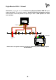
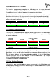
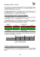
At the following sample the On-/Off switch function assign the four-fold address
block 1 to 4 and the WatchDog-Function the addresses 5 to 8.
The On-/Off switch function will be controlled by the address 3 and the WatchDog-
Function with the address 5.
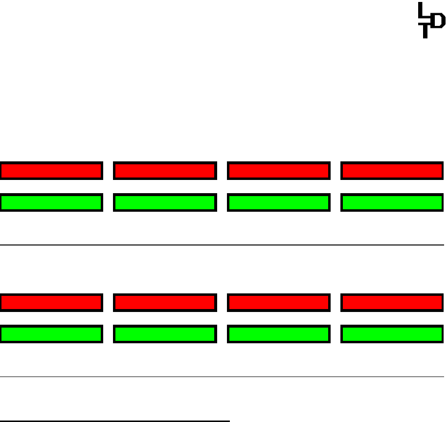
On-/Off sw. Function
not used not used Stop not used
round / red / - round / red / - round / red / - round / red / -
1 2 3 4
straight / green / + straight / green / + straight / green / + straight / green / +
not used not used Go not used
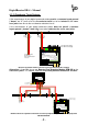
On-/ Off sw. Function
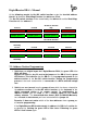
WatchDog
inactive not used not used not used
round / red / - round / red / - round / red / - round / red / -
5 6 7 8
straight / green / + straight / green / + straight / green / + straight / green / +
active not used not used not used
WatchDog
7.3. Address Section Programming:
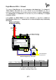
1. Switch-on your digital layout incl. DigitalBooster DB-4 (the green LED of the
DB-4 will glow).
Depress 1x short the key S1 next to the jumpers of the DB-4. Now the green
LED flashes. This indicates that the DB-4 is in the programming mode for the
address-section of the On-/Off switch-function. During the programming
process is the track section which is connected to the DB-4 switched voltage
free.
2. Switch now one turnout from the group of four which has been selected for
the address section of the On-/Off switch function via the keyboard of the
digital command station or the remote control. For programming the
address section you can send as well a turnout signal via your model
railway software. The transmitted data format (DCC or Märklin-Motorola)
has to match the data format you have selected with the jumper J4.
Remarks: It does not matter which of the four addresses from a group you
will use for programming.
If the DigitalBooster DB-4 understands the address the DB-4 will confirm the
assignment by flashing the green LED a little faster. Following the green
LED will flash slower again.