
User manual


Littfinski DatenTechnik (LDT)
Multi-Digital
Light emitting diodes have to be assembled that the long wire of the diode
corresponds to the mark "+" of the pc-board. Before assembly please slip the distance
spacer onto the connection wires.
The resistor-network RN1 is marked at one end for the assembly position with
“...103...” and additionally with a printed circle or a square. Assemble this component
that way that the marking corresponds with the marking at the first bore of the pc-
board. Additionally is the first bore marked with “1”.
Integrated circuits (IC`s) are either marked with a half round notch on one end or a
printed point for the correct mounting position. Push the IC`s into the correct socket
assuring that the notch or the printed point is corresponding to the half-rounded
marking on the pc-board. The 4-poles integrated circuit LTV814 (IC6) shall be
soldered directly onto the pc-board.
Please attend to the sensitivity of the ICs to electrostatic discharge, which will cause
immediate damage of the IC. Before touching those components please discharge
yourself by contacting an earthed metal (e.g. earthed radiator) or work with an
electrostatic safety pad.
Assembly of the DB4-Power PC-Board:
After completing the DB-4 basic pc-board you can assemble the SMD-pre-assembled
and tested DB4-Power PC-Board.
Firstly please tighten the two distance spacer to the basic pc-board with two of the four
cross section screws.
Apply now the DB4-Power PC-Board into the socket bar BU4 of the basic pc-board.
Pay attention that there is no offset of the DB4-Power PC-Board to the socket. The
DB4-Power PC-Board is in correct position at the socket bar BU4 of the basic pc
board if you can screw the DB-Power PC Board to the distance bolts.
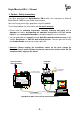
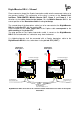
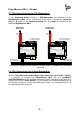
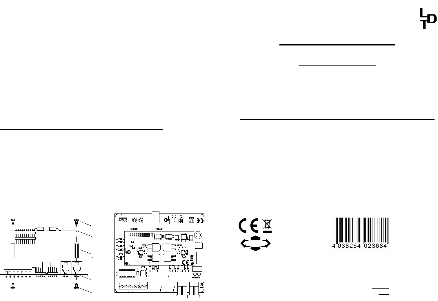
The following picture 1 show the assembly procedure from the side view and the
picture 2 show the assembled DB4-Power-PC Board onto the basic PC-Board with
sight from the top.
Schraube
screw
DB-4-Basis
Distanzbolzen
distance spacer
DB4-Power
Schraube
screw
DB4-Power
Rev. 1.4
Littfinski DatenTechnik (LDT)
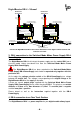
IC4 IC5
ST1
C3
R6
R5
D7
D5
C11
R1
D3
D2
IC1
R3
C4
C7
C8
C1 C2
C10
IC3
C9
D6
C6
R2
IC2
D1
D4
R4
C5
T1
T3
T4
T2
1 3 5 7 9 11 13
15
17 19
2 4 6 8
10 12 14 16 18 20
JP5
2,5
4,5
ShortReport
RailCom
GoAuto
ON OFF
JP4
JP3
JP2
JP1
MM DCC
BU1
DB-4
Rev. 1.4
JK
Littfinski DatenTechnik (LDT)
+
STOPGO
LED2LED1
red brown
S1
+
KL3KL4KL2
STOP/GO
EDC
BU2
BU3
ST2ST1
IN OUT
Feedback
A
T
KL1
Picture 1 Picture 2
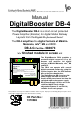
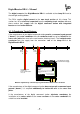
DigitalBooster DB-4
from the Digital-Professional-Series !
DB-4-B Part-No.: 080071
>> kit <<
The DigitalBooster DB-4 is a short-circuit-proofed power
amplifier (booster) for digital model railway layouts.
It provides a maximum digital current of 2,5 or 4,5 Ampere.
The DB-4 amplifies the digital formats of Märklin-Motorola,
mfx
®
, M4 and DCC.
The DB-4 can operate on several digital command stations
by using the 5-poles booster bus, the CDE-booster bus or
the Roco-booster bus.
The DigitalBooster DB-4 receives the power supply not from
a classical model railway transformer but from the switched
mode mains power supply DB-4 PowerSupply. On this unit is
the stabilized digital track voltage adjustable between 15 and
24 Volt, suitable for all track gauges.
This product is not a toy! Not suitable for children under 14 years. Improper use will imply danger or injuries due
to sharp edges and tips! Please store this instruction carefully.
CE Part-No.:
1370364
Made in Europe by
Littfinski DatenTechnik (LDT)
Kleiner Ring 9
D-25492 Heist/Germany
Phone: 0049 4122 / 977 381
Fax: 0049 4122 / 977 382
Internet: http://www.ldt-infocenter.com
Subject to technical changes and errors. 07/2015 by LDT
Märklin, Motorola and mfx are registered trademarks.
Assembly Instruction