
Installation Guide

Multi-Piece Sectional Product
Installation Instructions
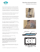
with a two piece back wall, the valve probably will be installed
through the lower wall panel. Make certain the valve does not
conict with the mounting ange or seam. Read the installation
instructions provided by the valve manufacturer. Before the Trial
t, carefully drill the valve hole (s) in the panel. When drilled,dry
Trial t the back wall panel (s) on the shower pan to test the t.
Conrm the gap where the wall seats to the pan is 1/8” or less.
Make sure the seam for the two piece wall is also 1/8” or less.
Adjust the valve hole size and location if required.
Lift the wall panel with the valve hole away. Complete the valve
installation and connection to hot and cold water supply at this
time. Also complete shower supply connection. Strap pipes to
framing if required. This is the last access to the plumbing before
the wall is permanently installed.
21. If all ts are good, proceed with the installation of the the
back wall. The installation procedures described in this step apply
for installation of one or two piece back walls.
Wipe clean the ledges on top of the pan. Apply a continuous
bead of 100% RTV silicone caulking along the back ledge of the
pan where the back wall will sit. The bead should be placed at
the middle of the ledge, and be 3/8” wide. The bead should go
completely around each alignment pin.
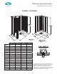
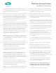
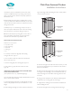
There are slots on the underside of the wall. There are alignment
pins in the pan that will insert into the slots on the bottom of the
wall. See the detail in Figure 19.
The lower section of the back wall is the panel with a single,
molded soap dish. Lift this panel up and carefully lower it onto
the back ledge on the pan.
Push the wall panel down to seat it in the caulking.
Check the t for level and plumb.
Note to installer: There is a difference having the bubble
between the lines and a plumb wall. The wall must be
VERY plumb or a gap larger than 1/8” will be present
where the side walls mate the back wall. Use wood shims
or furring strips to ll any space between the back wall
ange and the studs.
Align the wall section where it meets the shower pan so it is
centered on the pan, and install wood shims or furring strips if
necessary.
Pre-drill the mounting anges. Attach the wall with screws
17.
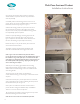
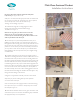
After the adhesive and thin-set materials are in place, rotate
the pan back into place for installation.
(Hint) In order to reach the pan without stepping on the adhesive,
place a short piece of wood over the drain area. Use this to step
on to remove the 2 x 4 that is holding the pan against the back
framing. (See Figure 15).
18.
19.
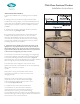
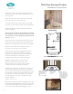
Before installing the walls, confirm the ledges
where the walls sit are level. Check with a long
level as shown in Figure 16. If there is an out of level
condition, remove screws and adjust as required.
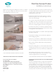
Before the adhesive cures, confirm the floor slope to the
drain has been maintained. To do this, use a 2 foot level at
various points around the drain to the adjacent wall to check
for draft. Make sure there is a downward slope to the drain in
all directions around the drain. Visually inspect the floor to be
sure there are no humps or dips that could cause improper
drainage.
See Figure 17A and 17B.
Rotate the pan back to the horizontal position. As you lower the
pan to the sub floor, align the drain pipe with the drain fitting,
and with the pencil mark at the front of the threshold.
NOTE: The working life of the flooring adhesive is roughly
one hour. (Refer to the label on the adhesive for actual
working time). After step 16 is complete, the entire
installation process though step 23 must continue. If for
any reason the installation cannot be completed within the
working time of the adhesive, after step 16, jump ahead to
step 23.
When the pan is seated into the adhesive, place the cardboard
on the shower floor for protection. Thoroughly walk around in
the shower. This will assist in seating the pan into the adhesive.
Attach the pan to the studs by installing the flat top/pan
head screws through the holes drilled into the flange.
Snug the screws up tight so the screw heads will be clear
of the side wall panels for assembly. Use care not to
overtighten to the point that causes flange breakage.
Figure 16
8
Figure 17B
Figure 17A
2 Ft. Level
Floor Level To
Drain - No Humps
Figure 15
Wood
7