LAUREATE SERIES SCALE / WEIGHT METER OWNERS MANUAL Now with USB & Ethernet LAUREL Electronics Inc. 3183-G Airway Ave, Costa Mesa, CA, 92626, USA Tel: (714) 434-6131 • Fax: (714) 434-3766 • Website: www.laurels.
1. ORDERING GUIDE Configure a model number in this format: LW20201SG1, CBL01 LW ........... Laureate scale / weight meter Input Type Display Color Process Signals (4-20 mA, 0-10V, etc.) 1 .............................DPM with green LED 2 .................................DPM with red LED P............................. 4-20 mA = 0-100.00 P1……………. ...............Custom Scaling Power Specify min signal & reading, max signal & reading. 10 Vdc excitation. 0 ...........................................
2. TABLE OF CONTENTS 1. 2. 3. 4. ORDERING GUIDE ..................................................................................................... TABLE OF CONTENTS............................................................................................... PRODUCT INTRODUCTION....................................................................................... ADVANCED OPERATING FEATURES....................................................................... 2 3 4 5 5. 5. 7. 8.
3. PRODUCT INTRODUCTION The Scale Meter is a compact, inexpensive, and extremely accurate digital panel meter with special firmware for weighing applications. It is available with a load cell or a DC signal conditioner board. The load cell signal conditioner board accepts full-scale ranges of ±20, ±50, ±100, ±250 and ±500 mV with 4- or 6-wire load cell hookup to display up to 99,999 counts. With 4-wire hookup, the meter operates in a ratiometric mode to eliminate errors due to supply variations.
4. ADVANCED OPERATING FEATURES • Setpoint offset. The ON/OFF setpoint control action can be programmed to occur with a specified offset. For instance, if bags are to be filled to 100 lbs and the material delivery spout is known to hold and dispense an additional 2.5 lbs following shut-off, an offset of -2.5 lbs can be programmed. The setpoint can then be set to 100 lbs, and the filling valve will be automatically shut off when the measured weight reaches 97.5 lbs. • Dribble factor.
5. RECEIVING & UNPACKING Your scale meter was carefully tested and inspected prior to shipment. Should the meter be damaged in shipment, notify the freight carrier immediately. In the event the meter is not configured as ordered or the unit is inoperable, return it to the place of purchase for repair or replacement. Please include a detailed description of the problem. 6.
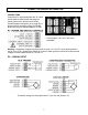
. CONNECTOR WIRING INFORMATION CONNECTORS Connectors for signal and power are UL-rated screw-clamp terminal blocks that plug into mating jacks on the printed circuit board. Communication connectors are a single RJ11 plug for RS232, dual RJ11 plugs for RS485, dual RJ45 plugs for RS485 Modbus, or USB. * Control inputs 1 & 2 of P1 are menu selectable. Warning: Hazardous voltages may be present on pins 4, 5 & 6 of P1 since digital ground is tied to pin 3 of P5 (-Signal Input).
P3 - SERIAL COMMUNICATIONS RS232 INTERFACE N/C ISO GND RX TX RTS N/C 6 5 4 3 2 1 P4 - ANALOG OUTPUT Computer GND TX RX RTS RS485 INTERFACE - FULL DUPLEX ISO GND BRX ARX ATX BTX ISO GND GND BTX ATX ARX BRX GND 6 5 4 3 2 1 RS485 INTERFACE - HALF DUPLEX ISO GND ATX / ARX BTX / BRX ISO GND RS485-MODBUS - FULL DUPLEX (A') RXD0 (B') RXD1 + (B) TXD1 * (A) TXD0 ISO GND 1 2 3 4 5 6 7 8 GND 6 5 4 3 2 1 ATX / ARX BTX / BRX GND RS485-MODBUS - HALF DUPLEX TXD0 TXD1 RXD1 RXD0 (B) TX / RXD1 (A) TX / RXD0 G
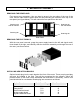
8. MECHANICAL ASSEMBLY REMOVING THE REAR PANEL First remove any connectors. Use one hand to press in the two sides of the rear of the case, and the other hand to press down the two protruding tab releases at the top of the rear panel (see figure below). This will unhook the rear panel from the case.
Note: Corresponding main board and option board connectors have the same number of electrical lines. When an option board is correctly installed, the top and bottom edges of the main board and option board are aligned. REASSEMBLING YOUR METER Slide the electronics assembly into the case until the display board is seated flush against the front overlay. Insert the bottom tabs of the rear panel into the case, and then carefully align the board connectors with the openings in the rear panel.
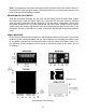
9. FRONT PANEL SETUP KEYS Meter Front Panel There are four front panel keys, which change function for the Run Mode and Menu Mode, effectively becoming eight keys. The keys are labeled with alphanumeric captions (MENU, PEAK, RESET, ALARMS) for the Run Mode and with symbols ( right arrow, right triangle, up triangle, left arrow) for the Menu Mode.
KEYS IN MENU MODE Right Arrow Key (MENU). Pressing steps the meter through all menu items that have been enabled and then back to the Run Mode. With the DC signal conditioner board and no option boards, available menu items are _InPut, SEtuP, ConFG, _FiLtr, dEc.Pt, SCALE, OFFst, Loc 1, Loc 2, Loc 3. If a change has been made to a menu item, that change is saved to non-volatile memory when the key is pressed next, and StoreE is displayed briefly. Right Triangle Key (Digit Select).
10. ENABLING & LOCKING OUT MENU ITEMS For security reasons and ease of meter operation, any and all menu items may be disabled or "locked out" so that they are no longer accessible from the front panel. Each function to be disabled can be set to "1" in menu items Loc 1 through Loc 4, and each function to be enabled can be set to "0." The Loc menu items can in turn be locked out by installing an internal hardware jumper. With the jumper installed, the operator only has access to enabled menu items.
11. PROCESS & STRAIN INPUT JUMPERS Process and strain input scale meters utilize the DC signal conditioner board, which offers sensitivity to ±200 mV and can operate in a ratiometric mode, which removes effects caused by variations in the excitation supply. This board needs to be configured via jumpers for the desired voltage or current range. All signal ranges are factory calibrated with calibration factors stored in EEPROM.
12. LOAD CELL INPUT JUMPERS Load cell scale meters utilize the load cell signal conditioner board, which offers sensitivity to ±20 mV full scale and 4- or 6-wire load cell connection. This board needs to be configured via jumpers for the desired voltage range. All signal ranges are factory calibrated with calibration factors stored in EEPROM. The meter software recognizes the board and will bring up the appropriate menu items for it; however, it does not recognize the jumper settings.
13. SCALE METER SETUP When the Reading Coordinates of 2 Points scaling method has been selected under SEtuP, the four menu items below will appear ahead of all other menu items when the MENU or key is first pressed from the run mode. This scaling method applies a straight line fit between two points, which are determined from actual transducer signals and the desired corresponding meter readings.
OTHER KEYSTROKES FOR SCALE METER SETUP key does not work, see Section 10 “Enabling & Locking Out Menu Items.” If the MENU Press Menu Select Key _InPut DC signal conditioner board Press Digit Select Key Press Value Select Key _dC U DC Volts __0.2U __2.0U _20.0U 200.0U 600.0U 0.2, 2, 20, 200, 660V FS _dC A DC Amps __2.0A _20.0A _200.0A _5.0A 0.2, 20, 200 mA, 5A FS _rAtio Strain gauge & ratio __0.2U __2.0U _20.0U 0.2, 2, 20V FS.
Press Menu Select Key Press Digit Select Key ConFG 00000 Meter Configuration Negative readings Count Count-by or Auto-zero function FiLtr Filtering Press Value Select Key 0 Allow negative readings 1 Disallow negative readings 00000 Setup method 0 Scale & offset method 1 Reading coordinates of 2 points method 00000 Dribble function 0 Dribble enabled 1 Dribble disabled 00000 Peak key action 0 Peak of net value 1 Peak of Gross value 00000 Adaptive filtering 0 Enable adaptive filtering 1 Disable ad
FiLtr Filtering (continued) 00000 Input signal filtering. Can be applied to display, setpoint, analog output, data output. 0 1 2 3 4 5 6 7 8 9 A B C D E F Autofilter Readings Batch avg 16 60 Hz Moving avg . 07 s Moving avg .14 Moving avg .28 Moving avg .57 Moving avg 1.13 Moving avg 2.27 Moving avg 4.53 Moving avg 9.06 Moving avg 18.1 Moving avg 36.2 Moving avg 72.5 Moving avg 145 Moving avg 290 No filter d.dddd Decimal point flashes. d.dddd dd.ddd ddd.dd dddd.d ddddd. .
Option board dependent menu items ALSEt. -SP1-d -SP2-d Menu items related to alarm setup These will only appear if a relay board is detected. If so, please see Section 14. AnSEt. An Lo. An Hi.. Menu items related to analog output setup. These will only appear if an analog output board is detected. If so, see Section 15. SEr 1. SEr 2. SEr 3. SEr 4. _Addr Menu items related to serial communications. These will only appear if an RS232 or RS485 I/O board is detected. If so, see Section 16.
14. DUAL RELAY OUTPUT OPTION An optional relay board may be installed in the scale meter main board at plug position P2, adjacent to the power supply board. This board is available in two versions: 2 mechanical relays or 2 solid state relays. Once installed, the relay board is recognized by the meter software and PC-based Instrument Setup software, which will bring up the appropriate menu items for the board type. These menu items will only be brought up if a relay board is detected.
Press Menu Select Key Press Digit Select Key _SPI_d Alarm 1 dribble value 0.0000 0.0000 0.0000 0.0000 0.0000 Select digit to flash. _SP2_d Alarm 2 dribble value 0.0000 0.0000 0.0000 0.0000 0.0000 Select digit to flash. Press Value Select Key Select -9 thru 9 for flashing first digit, 0 thru 9 for other flashing digits. Active high alarms will activate above the setpoint (positive dribble value) or below the setpoint (negative dribble value).
ALARM TYPES Latched alarms stay actuated until reset. They can shut down machinery or a process when a setpoint (or limit) has been exceeded or maintain an alarm condition until acknowledged by an operator. Non-latched alarms change state automatically when a reading rises above a setpoint and change back automatically when the reading falls below that setpoint. Dribble is a settable scale meter parameter in counts which allows a flow to be shut off before the setpoint value has been reached.
15. ANALOG OUTPUT OPTION An analog board may be installed in the meter at rear panel jack position J4, adjacent to the signal conditioner board. Once installed, this board is recognized by the meter, which will bring up the appropriate menu items for it. These will not be brought up if an analog output board is not installed. The analog output can be a 0-20 mA, 4-20 mA or 0-10V unipolar signal with respect to isolated ground, or a bipolar -10V to +10V voltage signal with respect to a reference return line.
16. SERIAL COMMUNICATION OPTIONS A serial communications board may be connected to the meter main board at plug position P13 (middle position). Available boards are RS232, RS485 (with dual RJ11 connectors), RS485 Modbus (with dual RJ45 connectors), USB, USB-to-RS485 converter, Ethernet, and Ethernet-to-RS485 converter. The dual connectors of RS485 boards are wired in parallel to allow daisy chaining of addressable meters without use of a hub.
Basic Ethernet Board No jumpers needed. RS232 Board e - Normal operation. f - Slave display to RS232 from another meter. g - Pull-up resistor on RTS line. Note: Board is shipped with jumpers e and g installed RS485 Board, Full Duplex Operation b & d - Installed on last meter in long cable run. RS485 Board, Half Duplex Operation a & c - Installed for half duplex operation. d - Installed on last meter in line with long cable runs. Note: Board is shipped with no jumpers installed.
SERIAL CONNECTION EXAMPLES 27
KEYSTROKES FOR SETUP If the MENU key does not work, see Section 10 “Enabling & Locking Out Menu Items.” Press Menu Select Key .SEr 1. Fixed Parameters: No parity 8 data bits 1 stop bit Press Digit Select Key Press Value Select Key __000 Output signal source 0 Send unfiltered value 1 Send filtered value __000U Baud rate 0 1 2 3 4 5 6 300 baud 600 baud 1200 baud 2400 baud 4800 baud 9600 baud 19200 baud 0 1 2 3 4 5 6 7 8 9 60 Hz Line frequency 0.28 sec 0.57 sec 1.1 sec 2.3 sec 4.5 sec 9.1 sec 18.
Press Menu Select Key .SEr 2. Serial Setup 2 .SEr 3. Serial Setup 3 SEr 4. Serial Setup 4. _Addr Modbus Address. Appears only if the Modbus protocol is selected.
17. EXCITATION OUTPUT & POWER SUPPLY Three isolated transducer excitation output levels are available from the power supply board. These are selectable via jumpers b, c, d, e, f in the upper right of the board, as illustrated. In addition, the board provides three jumper positions for special features. The same jumper locations apply to the universal power supply (85-264 Vac) and to the low voltage power supply (12-32 Vac or 10-48 Vdc).
18. INSTRUMENT SETUP VIA PC Instrument Setup software is a PC program which is much easier to learn than front panel programming. It is of benefit whether or not the meter is connected to a PC. With the meter connected to a PC, it allows uploading, editing and downloading of setup data, execution of commands under computer control, listing, plotting and graphing of data, and computer prompted calibration.
SETUP OF CONNECTED METER A setup file can be retrieved from the meter (DPM => Get Setup), be edited (View => Setup), be saved to disk (File => Save Setup), be retrieved from disk (File => Open Setup), and be downloaded into one or multiple meters (DPM => Put Setup). Downloading of setup files from a PC can be a major time saving when multiple meters have to be set up in the same way.
Plot Graph • The Readings pull-down menu provides three formats to display DPM data on the PC monitor. Use the Pause and Continue buttons to control the timing of data collection, then press Print for a hardcopy using your PC printer. - List presents the latest readings in a 20-row by 10-column table. Press Pause at any time to freeze the display. Press Print for a hardcopy. List can capture peak readings. - Plot generates a plot of readings vs. time in seconds.
To enter new setup information, click on View => Setup, then make your screen selections as if you were connected to a meter. Tabs will be grayed out if you have not selected the required hardware under the Input+Display tab. When done, press on Main Menu, then on View => Menu.
20. SCALE METER SPECIFICATIONS Meter Display Type ....................................5 LED, 7-segment, 14.2mm (.56") high digits & 3 LED indicators Color....................................................................................................................Red or green Range.................................................................... -99999 to +99999 and -99990 to +99990 A to D Conversion Technique (Pat.5,262,780)........................................................................
DC, Process, Strain Signal Conditioner Range Resolution Resistance Zero Range Span Range Error 200.00 mV 2.0000 V 20.000 V 10 µV 100 µV 1 mV 1 GΩ -99999 to 99999 0 to ±99,999 0.01% of FS ±2 cts at 25°C Load Cell Signal Conditioner Range Resolution Resistance Zero Range Span Range Error 20.000 mV 50.000 mV 100.00 mV 250.00 mV 500.00 mV 1 µV 2.5 µV 5 µV 12.5 µV 25 µV 1 GΩ -99999 to 99999 0 to ±99,999 0.01% of FS ±2 cts at 25°C Dual Relay Options Power to Relay Option ..................
Accuracy ..........................................Meter input accuracy ±0.02% of full scale analog output Resolution ...........................................................................................16 bit (1 part in 65,536) Response Time ....................................................................................... 50/60Hz update rate Scaling of Reading for Zero Output ........................................................... -99,999 to +99,999 Scaling of Reading for Full Scale Output.
21. GLOSSARY OF TERMS Adaptive Filter Threshold A threshold which causes an adaptive moving average filter to be reset to the latest reading when the accumulated difference between individual readings and the filtered reading exceeds that threshold. Adaptive moving average filtering allows a meter to respond rapidly to actual changes in signal while filtering out normal noise. The accumulated difference is also reset to zero when the latest reading has a different polarity than the filtered reading.
Custom ASCII Protocol A simplified, short protocol for use with these panel meters. It allows 31 digital addresses. Not an industry-standard protocol, like the more complex Modbus protocol, which is also offered with the meters. Display Blank A rear panel input which blanks the display when the input is tied to logic ground by a switch or 0V is applied (logic level true). The meter display will light when the input is open or is held at +5V (logic level false).
Meter Hold A rear panel input which freezes the meter display and all meter outputs while that input is tied to logic ground by a switch or is held at 0V (logic level true). The meter will resume operation when the input is allowed to float or is held at +5V (logic level false). Modbus An industry-standard serial communications protocol which allows devices by different manufacturers to be digitally addressed by a PC on the same communication line, with up to 247 digital addresses.
Reset There are three types of Reset: Peak Reset. Achieved by simultaneously pressing the RESET and PEAK keys. Latched Alarm Reset. Achieved by simultaneously pressing the RESET and ALARMS keys. Meter Reset. Causes the meter to reinitialize and take a tare reading when set up for auto-tare. Achieved powering up the meter, by pressing the RESET and MENU keys simultaneously, stepping through all top-level menu choices, grounding a rear panel connector, or supplying an ASCII command.
voltage or current at either point does not need to be known. The decimal point is set by the separate dEC.Pt menu item. Setpoint A value compared to the reading to determine the state of a relay. Term often used interchangeably with “alarm setpoint.” The relay action can by latching or non-latching, utilize a hysteresis band, or utilize a deviation band. Hysteresis bands and deviation bands are specified by two symmetrical limits around the setpoint.
22. WARRANTY Laurel Electronics Inc. warrants its products against defects in materials or workmanship for a period of one year from the date of purchase. In the event of a defect during the warranty period, the unit should be returned, freight prepaid (and all duties and taxes) by the Buyer, to the authorized Laurel distributor where the unit was purchased. The distributor, at its option, will repair or replace the defective unit.