LAUREATE SERIES DPM OWNERS MANUAL LAUREL Electronics Inc. 3183-G Airway Ave, Costa Mesa, CA USA 92626 Tel: (714) 434-6131 Fax: (714) 434-3766 Website: www.laurels.
ORDERING GUIDE L .... Laureate series meter with screw terminal connectors. Display Color 1 ............... DPM with green LED 2 ................... DPM with red LED 3 ...... Extended DPM/green LED 4 ......... Extended DPM/red LED Note: Extended versions add rate of change and linearization of non-linear input signal capabilities. Not available for thermocouple or RTD inputs DC Volts DCV1 ................ 200.00 mV DCV2 ................... 2.0000 V DCV3 ................... 20.000 V DCV4 ...................
CONTENTS 1. 2. 3. 4. 5. 6. 7. 8. 9. 10. 11. 12. 13. 14. 15. 16. 17. 18. 19. 20. 21. 22. 23. 24. 25. INTRODUCTION ....................................................................................................... 2 RECEIVING AND UNPACKING ................................................................................ 3 SAFETY CONSIDERATIONS ................................................................................... 3 CONNECTOR WIRING INFORMATION ...............................................
1. INTRODUCTION This series of panel instruments is a versatile, cost effective solution to a wide variety of monitoring and control applications. These instruments are easily set to produce an accurate display of temperature, pressure, flow, weight, voltage or current. Front panel push-button or RS-232/RS-485 setup allows the user to customize the unit for a specific application. Digital scaling of zero and span provides direct readout in engineering units.
2. RECEIVING AND UNPACKING Your meter was carefully tested and inspected prior to shipment. Should the meter be damaged in shipment, notify the freight carrier immediately. In the event the meter is not configured as ordered or the unit is inoperable, return the unit to the place of purchase for repair or replacement. Please include a detailed description of the problem. 3.
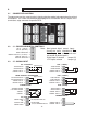
4. 4.1 CONNECTOR WIRING INFORMATION CONNECTOR LOCATION The connectors are the screw terminals that plug into the mating jack mounted on the printed circuit board. P3 is either a 6 conductor phone plug for RS-232 and RS-485 or a 30 pin, mass termination, edge connector for parallel BCD. J1 1 1 J5 J3 J2 1 6 1 J4 6 6 6 4.
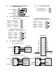
4.3 J5 - SIGNAL INPUT ( CONTINUED ) 4.4 LOAD CELL METER J5 -10 V EXCITATION 1 -SENSE 2 -SIGNAL 3 +SIGNAL 4 +10 V EXCITATION 5 +SENSE 6 4.5 J4 - ANALOG OUTPUT 0 TO 20 MA OUTPUT 0 TO 10 VDC OUTPUT ISOLATED GROUND 1 2 3 J 2 - DUAL SETPOINT CONTROLLER RELAY OUTPUTS ALARM 1 - N/O CONTACT ALARM 1 - N/C CONTACT ALARM 1 - COMMON 1 2 3 ALARM 2 - N/O CONTACT ALARM 2 - N/C CONTACT ALARM 2 - COMMON 4 5 6 SOLID STATE RELAY OUTPUTS Switching AC 125Vac @120 ma max.
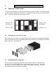
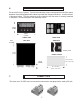
5. 5.1 MECHANICAL ASSEMBLY REMOVING THE REAR PANEL To remove the rear panel, first remove any connectors that are installed. Press down on both rear panel retaining tab releases(see Fig. 5.1) and pull the top of the rear panel away from the case. The bottom of the rear panel will now lift out. Retaining Tab and Release Retaining Tab and Release Retaining Tab Retaining Tab Figure 5.1 5.
6. PANEL MOUNTING Ensure the O-ring is in place. Turn the two mounting screws counterclockwise until the space between the mounting pawl and the bezel is greater than the panel thickness. Insert the meter in the panel cutout. Turn the mounting screws clockwise until the meter is securely mounted in the panel. Do not overtighten the mounting screws. 48mm (1.89in) 96mm (3.78in) 5mm (0.197in) J1 J2 J3 J4 FRONT VIEW REAR VIEW TOP VIEW SIDE VIEW J5 Mounting Pawl 102mm (4.
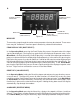
8. FRONT PANEL SETUP KEYS ALARM 1 STATUS INDICATOR MENU KEY PEAK DISPLAY KEY ( DIGIT SELECT ) ALARM 2 STATUS INDICATOR ALARM KEY (REVERSE MENU) Figure 8.1 RESET KEY ( VALUE SELECT ) MENU KEY The menu key steps through the various meter parameters that may be selected. These menu items may be “locked out” from front panel selection by software and hardware. PEAK DISPLAY KEY (DIGIT SELECT) In the Operating Mode, pressing the Peak Display Key causes the peak value of the input signal to be displayed.
9. SETTING MENU LOCKOUTS For security and ease of operation, any or all program menu items may be disabled. Each function to be disabled is set to "1" in the menu items, " Loc 1"," Loc 2" or "Loc 3". These lockout menu items may in turn be "locked-out" by installing an internal hardware shorting jumper. With the jumper installed, the operator has access only to enabled menu items. 9.1 SETTING HARDWARE LOCKOUT JUMPER Lockout Jumper a Power Supply Board Figure 9.1 9.
MENU KEY key until Loc Press the 2 is displayed. DIGIT SELECT KEY Press to display status and select left digit. Press again to select another digit. Selected digit will flash. "1" indicates the menu item is disabled. "0" indicates the item is enabled. VALUE SELECT KEY 2 3 4 5 Press to select "0" or "1" for flashing digit 2 - Alarm Setup 3 - Alarm setpoint value programming 4 - Analog output scaling 5 - Serial interface setup 2 key until Loc Press the 3 is displayed.
MENU KEY DIGIT SELECT KEY VALUE SELECT KEY TEMPERATURE SIGNAL CONDITIONER InPut Input signal type tC Thermocouple Note: Display =K rtd Pt 100 Ohm RTD J°F J°C K°F K°C t°F t°C E°F E°C S°F S°C r°F r°C n°F n°C Types J, K, T, E, N, S, R in °C or °F 4d °F 4d °C DIN 4-wire 4A °F 4A °C ANSI 4-wire 3d °F 3d °C DIN 3-wire 3A °F 3A °C ANSI 3-wire 2d °F 2d °C DIN 2-wire 2A °F 2A °C ANSI 2-wire Short Compensation for 2-wire lead resistance DC SIGNAL CONDITIONER dC U DC Volts 0.2U 2.0U 20.0U 200.0U 660.0U 0.
MENU KEY DIGIT SELECT KEY VALUE SELECT KEY LOAD CELL SIGNAL CONDITIONER InPut Input signal type (continued) SEtuP Meter Setup Strn Load cells 20.0 50.0 100.0 250.0 500.0 20, 50, 100, 250, 500 mV FS dC u DC millivolts 20.0 50.0 100.0 250.0 500.0 20, 50, 100, 250, 500 mV FS 00000 Display selection 0 4 1/2 digits (0.1 Degree) 1 Remote display 2 4 1/2 digits [meter counts by 10] (.
MENU KEY ConFG Meter Configuration DIGIT SELECT KEY 00000 Operates as a rate of change meter Extended version only 0 1 2 3 4 5 6 00000 Selection of scaling by reading input signal or by Setup selection 0 Use setup scaling method 1 Scale by reading input 00000 Selects between continuous (unlatched) data or single value (latched) of RS232 data when RTS is high or open 0 Unlatched 1 Latched 00000 RS485 interface operates in the full duplex or half duplex mode 00000 Scaling for nonlinear input Extended
DIGIT SELECT KEY VALUE SELECT KEY 00000 Adaptive filter response 0 Low threshold level 1 High threshold level 00000 Input signal filtering 0 1 2 3 4 5 6 7 8 9 A dEc.Pt Decimal point selection d.dddd d.dddd dddd.d (Scale and Offset selected) SCALE Scale factor multiplier (not available for tC) 0.0000 0.0000 0.0000 0.0000 0.0000 0.0000 Select 0 through 9 for flashing digit and decimal point location when decimal point is flashing OFFSt Offset or Zero Value 0.0000 0.0000 0.0000 0.0000 0.
MENU KEY DIGIT SELECT KEY VALUE SELECT KEY Hi rd High Displayed Reading at High Signal Input 0.0000 0.0000 rd0 In (custom curve only) Corrects for zero errors 04.000 Value set to actual voltage or current input at zero Select 0 through flashing digit. ALSEt Alarm Operation Setup (Only enabled if relay output is installed).
MENU KEY ALSEt (continued) Alarm Operation Setup DIGIT SELECT KEY 00000 Selection of Hysteresis mode or Band Deviation mode of alarms. 00000 Number of readings in the alarm zone to cause an alarm dEU1H 00000 00000 00000 Amount of deviation or 00000 00000 When the deviation value is hysteresis - Alarm 1 (Only enabled if relay output >0, the alarms operate above and below setpoint by the value is installed). entered.
MENU KEY DIGIT SELECT KEY VALUE SELECT KEY (if analog output installed) 0.0000 0.0000 An Lo Displayed value for 0 voltage or current output 0.0000 0.0000 0.0000 Select 0 through 9 for flashing digit. Decimal point location fixed by dEC.Pt selection. An Hi 0.0000 Displayed value for 10 volts or 0.0000 20 mA output 0.0000 0.0000 Select 0 through 9 for flashing digit. Decimal fixed by DEC.Pt selection. 0.
MENU KEY Ser 2 (continued) Serial interface setup DIGIT SELECT KEY 0000 Meter address for RS-232/RS485 communication ( digit display, address number of meter) Note: Addresses 1 through 15 are denoted by 1 through 9 and A through F. Addresses 16 through 31 use the same character followed by a decimal point. 0000 VALUE SELECT KEY Meter# 1 2 3 4 5 6 7 8 9 10 11 12 13 14 15 16 17 18 19 20 21 22 23 24 25 26 27 28 29 30 31 Loc 1 Lockout of Menu Items (Lockout jumper must be removed to access Loc 1, 2, 3.
MENU KEY DIGIT SELECT KEY VALUE SELECT KEY Loc 1 (continued) Lockout of Menu Items (Lockout jumper must be removed to access Loc 1, 2, 3. See Figure 9.1) 00000 Scale or Lo, Hi Input 0 Enabled 1 Disabled 00000 Offset or Lo, Hi Reading 0 Enabled 1 Disabled Loc 2 Lockout of Front Panel Keys (Lockout jumper must be removed to access Loc 1, 2, 3. See Figure 9.
11. DC VOLTS & AMPS 11.1 RANGE JUMPER SELECTIONS Voltage Input Jumpers Required 200mV E, b 2V E, a 20V F, g, b 200V F, g, a 660V F, h, a A B D Current Input Jumpers Required 2mA D, h, b 20mA C, h, b 200mA B, h, b 5A A, h, b F C E g h b a Figure 11.1 DC Signal Conditioner Voltage Input ±200.00 mV ±2.0000 V ±20.000 V ±200.00 V ±600.00 V FS Input ±2.0000 mA ±20.000 mA ±200.00 mA ±5.000 A 11.
MENU KEY DIGIT SELECT KEY VALUE SELECT KEY until dC U Press (dc Volts) is displayed Press to select 0.2V, 2.0V, 20.0V, 200.0V, 660.0V or dC A (DC Amps) is displayed. or 2.0a, 20.0a, 200.0a (milliamps) or 5.0A (Amps) 1 2 3 4 5 Press to display status and select left digit. Press again to select another digit. Selected digit will flash. 1 2 3 4 5 Press to select value for flashing digit. Digit 1: "0"= 20,000 cts. full scale "3"=2,000 cts.
12. 12.1 PROCESS SIGNAL INPUTS RANGE JUMPER SELECTIONS Voltage Input Jumpers Required 200mV E, b 2V E, a 20V F, g, b 200V F, g, a 660V F, h, a A B F C D E Current Input Jumpers Required 2mA D, h, b 20mA C, h, b 200mA B, h, b 5A A, h, b g h b a Voltage Input ±200.00 mV ±2.0000 V ±20.000 V ±200.00 V ±600.00 V E1 A A B B B E2 f f h h g E3 b a b a a Current FS Input E1 E2 E3 ±2.0000 mA A e, h b ±20.000 mA A d, h b ±200.00 mA A c, h b ±5.000 A A a,b,h b 12.
To set up the range using coordinates of 2 points, values for low signal input, low display, high signal input and high display are entered. The following example uses this scaling method. Signal input is 4 to 20mA and displayed value is 000.00 (at 4mA) to 100.00 (at 20mA). When setting up the meter, it may be necessary to enable some menu items. See Section 9 for further information. MENU KEY key to display Press the InPut (Input type selection).
DIGIT SELECT KEY MENU KEY Press the key to display Hi rd (Desired meter reading at high signal input). to display value Press and select left digit. Press again to select another digit. Decimal point set by Dec.Pt. VALUE SELECT KEY Use to set digit values and set to 000.00 . Press the key. Continue to press (or and simultaneously) until rESEt is displayed. The meter will now go to the operating mode and display the value of the input signal. 13. THERMOCOUPLES 13.
MENU KEY DIGIT SELECT KEY VALUE SELECT KEY Press the key to display InPut (Input type selection). Note: Selection of input type & range must match jumper selection in Section 13.1. Press to display input again selected. Press until tC (thermocouple) is displayed. Press to select thermocouple type J, K, T, E, R, S and °C or °F scale (J°F, J°C, K°F, K°C, t°F, t°C, E°F, E°C, r°F, r°C, S°F, S°C) Press the key to display SEtuP.
14. 14.1 Pt100 RTD'S RANGE JUMPER SELECTION e All RTD Types f Jumpers Required 2-,4-wire b, e a Jumpers Required 3--wire b a, e Note: See Section 22 to select 10 Vdc excitation. Figure 14.1 Temperature Signal Conditioner 14.2 2-WIRE RTD LEAD COMPENSATION This section describes how to remove the error caused by lead resistance in a 2-wire RTD. Ambient temperature changes will cause some error in the readings; the higher the lead resistance, the greater the error.
14.3 MENU SELECTIONS The following example is setup for a 4-wire DIN RTD. When setting up the meter, it may be necessary to enable some of the menu items. See Section 9 for further information. MENU KEY Press the key to display InPut (Input type selection). Note: Selection of input type & range must match jumper selection in Section 14.1.
15 STRAIN GAUGES AND POTENTIOMETERS 12.1 RANGE JUMPER SELECTIONS Voltage Input Jumpers Required 200mV E, b 2V E, a 20V F, g, b 200V F, g, a 660V F, h, a A B F C D E Current Input Jumpers Required 2mA D, h, b 20mA C, h, b 200mA B, h, b 5A A, h, b g h b a Voltage Input ±200.00 mV ±2.0000 V ±20.000 V ±200.00 V ±600.00 V E1 A A B B B E2 f f h h g E3 b a b a a Current FS Input E1 E2 E3 ±2.0000 mA A e, h b ±20.000 mA A d, h b ±200.00 mA A c, h b ±5.000 A A a,b,h b 15.
MENU KEY DIGIT SELECT KEY VALUE SELECT KEY 1 2 3 4 5 Press the key to display SEtuP. (Basic setup). See Section 9, Page 10 for detailed description of selections for digits 1 through 5. Press to display status. again to select Press another digit. Selected digit will flash. Press to select value. Digit 1:"0"= 20,000 cts. FS "2"=LSD fixed zero "3"=2,000 cts. FS Digit 4: "1" for 2 point scaling Press the key to display dEcPt (Decimal point). Press to display decimal point location.
16. AC (RMS) VOLTS & AMPS This section provides basic setup instructions for true RMS voltage or current monitoring. An RMS signal conditioner is required. Some menu items, such as leading zero blanking, display filtering, etc., are not discussed in this section and have been set to the most commonly used values. Should these items require change, refer to section 10 for selection information. For configuration of optional boards, see the appropriate section elsewhere in the manual. 16.
MENU KEY DIGIT SELECT KEY VALUE SELECT KEY until AC U Press (ac Volts) is displayed or Press to select 0.2V, 2.0V, 20.0V, 200.0V or 660.0V or AC A (ac Amperes) is displayed. 2.0a, 20.0a, 200.0a (milliamps) or 5.0A (Amps) Press the key to display SEtuP. (Basic setup). See Section 9, Page 10 for detailed description of selections for digits 1 through 5. Press to display status and select left digit. Press again to select another digit. Selected digit will flash.
17. LOAD CELLS AND MICROVOLT INPUTS This section provides setup instructions for use as a microvoltmeter or with load cells and strain gauges. 10 Volt excitation will power up to 4 350 Ohm load cells. Sense leads may be used to compensate for lead resistance of the excitation supply. For configuration of optional boards, see the appropriate section elsewhere in the manual. 17.
MENU KEY DIGIT SELECT KEY VALUE SELECT KEY key to display Press the ConFG(configuration). See Section 9, Pg 13 for detailed description of digits 1 thru 5. Press to display status. Press again to select digit. Selected digit will flash. 1 2 3 4 5 Press to select value. Digit 2:"1"= Reading input 2 coodinate method of scaling. Press the key to display dEcPt (Decimal point). Press to display decimal point location. to change decimal Press point location. Press the key.
18. DUAL ALARM OUTPUTS 18.1 OPERATING MODE MENU SELECTION When setting up the meter, it may be necessary to enable some of the menu items. See Section 9 for further information. MENU KEY DIGIT SELECT KEY VALUE SELECT KEY 1 Press the key until ALSEt (Alarm setup) is displayed. See Section 9, ALSEt for detailed selection information for Digits 1 through 5. 2 3 4 5 Press to display status. Press to select value for Press again to select flashing digit digit. Selected digit will flash.
18.3 BAND DEVIATION When deviation is selected from the setup menu, a value is entered for the amount of deviation required. This value represents the number of counts at which the relay will be energized above and below the setpoint. For example, if the setpoint is set to 10,000 and a deviation value of 200 was entered, the relay will activate below 9800 and above 10,200. 18.4 HYSTERESIS When hysteresis is selected from the setup menu, a value is entered for the amount of hysteresis required.
19. ANALOG OUTPUT The analog output option provides a 0 to 20mA and a 0 to 10Vdc linear signal derived from the displayed reading. The low signal output and high signal output may be set to equal any displayed value. Although both outputs are available, only one is calibrated to specifications. The other output is accurate to +/-1% of the displayed value typical (2%max). 19.
20. RS-232 AND RS-485 INTERFACE 20. 1 OPERATING MODE MENU SELECTION The following menu items are accessible only with an RS-232 or RS-485 option installed and appropriate lockouts enabled. See Section 10 for further information. MENU KEY Press the key until SEr 1 (Serial interface setup 1) is displayed. Press the key until SEr 2 (Serial interface setup 2) is displayed. DIGIT SELECT KEY 1 2 3 4 5 to display status. Press Press again to select digit. Selected digit will flash.
15. RS-232 AND RS-485 INTERFACE 15. 1 JUMPER SELECTIONS RS232 Interface Jumper g - installed for normal operation Jumper h - installed when used as a slave display with the RS232 output of another Laureate meter. Jumper j - provides a pull-up resistor on the RTS line. g h j Note: The board is shipped standard with jumpers g and j installed RS232 RS485 Interface Note: Bias jumpers b and e must be installed on board for proper operation.
21. PARALLEL BCD OUTPUT 21. 1 OPERATING MODE MENU SELECTION The following menu items are accessible only with a BCD option installed and appropriate lockouts enabled. See Section 9 for further information. MENU KEY DIGIT SELECT KEY 1 Press the key until SEr 1 (Serial interface setup 1) is displayed. 2 3 4 5 Press to display status. Press again to select digit. Selected digit will flash.
22. 5, 10 AND 24 VDC EXCITATION OUTPUTS b c d e f h g a Figure 22. 1 - Power Supply 22. 1 SELECTION OF 5, 10 OR 24VDC OUTPUT Voltage Output 5 Vdc 10 Vdc 24 Vdc Jumper Locations b, d and e b, d and f c b d b d e 5 Vdc f 10 Vdc c 24 Vdc 22. 2 SELECTION OF OTHER JUMPERS Jumper ' a ' - Front panel menu lockout, locked when installed (see Section 10.
23. 23.1 DIGITAL INPUTS FUNCTION OF DIGITAL INPUTS Tare Logical 0 - The present display value is set to zero and stored as an offset value. Logical 1 - The displayed value is equal to the signal input minus the tare value. Peak Display Logical 0 - The peak value of the input signal is displayed. Logical 1 - The present value of the input signal is displayed. Hold Logical 0 - The meter display and outputs are held at the last reading.
24. CALIBRATION All ranges of the meter have been digitally calibrated at the factory prior to shipment. The calibration equipment is certified to NIST standards. Calibration constants are stored in nonvolatile memory in EEPROM on the signal conditioner. This eliminates much of the analog circuitry that causes drift and provides superior long term accuracy and stability.
ACCURACY DC Volts RTD's (.01, .1, 1.0 Degree Resolution) VOLTAGE RANGE RESOLUTION 200.00 mV 2.0000 V 20.000 V 200.00 V 660.0 V 10 uV 100 uV 1 mV 10 mV 100 mV INPUT OHMS ERROR AT 25°C PT100 TYPE RANGE ERROR AT 25°C 1G 1G 1M 1M 1M .01% Full Scale +/-2 Ct. DIN .00385 -202°C to +850°C -331°F to +1562°F .01% FS +/- 0.03°C .01% FS +/- 0.05°F ANSI .003925 -202°C to +631°C -331°F to +1168°F .01% FS +/- 0.04°C .01% FS +/- 0.07°F DC Amperes CURRENT RANGE RESOLUTION 2.0000 mA 20.000 mA 200.00 mA 5.
Span Tempco ....................................................................................... 0.003% of reading/°C Load Cell Meter only .................................................................. 0.0015% of reading/°C Zero Tempco ........................................................................................................... 0.2 uV/°C Reference Junction ................................................................................. 0.
Isolation Coil to Contacts ...................... Safety-rated to 250Vac, 4.2kVp per High Voltage Test Between Open Contacts ................................................... withstand 4.2kVp for 1 min Pickup .......................................................................................................... 26 ms typ. Release ....................................................................................................... 22 ms typ. Solid State Relay Output Voltage Rating ....................
WARRANTY Laurel Electronics Inc. warrants its products against defects in materials or workmanship for a period of one year from the date of purchase. In the event of a defect during the warranty period, the unit should be returned, freight prepaid (and all duties and taxes) by the Buyer, to the authorized Laurel distributor where the unit was purchased. The distributor, at its option, will repair or replace the defective unit.