LAUREATE SERIES COUNTER/TIMER OWNERS MANUAL LAUREL Electronics Inc. 3183-G Airway Ave, Costa Mesa, CA USA 92626 Tel: (714) 434-6131 Fax: (714) 434-3766 Website: www.laurels.
ORDERING GUIDE L ........... Laureate series counter/timer with screw terminal connectors. Display Color 5 ................................................ Green LED 6 ....................................................Red LED 7 ............................... Extended capabilities, custom curves, Green LED 8 ...............................
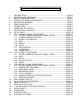
TABLE OF CONTENTS 1. 2. 3. 4. 5. 6. 7. 8. 9. 10. 11. 12. 13. 14. 15. 16. 17. 18. 19. 20. 21. 22. INTRODUCTION........................................................................................................PAGE 2 RECEIVING AND UNPACKING ..............................................................................PAGE 3 SAFETY CONSIDERATIONS ..................................................................................PAGE 3 CONNECTOR WIRING INFORMATION ......................................
1. INTRODUCTION The series of panel instruments is a versatile, cost effective solution to a wide variety of monitoring and control applications. These instruments are easily set to produce an accurate display of frequency, rate, total, period, time interval, phase, position , flow, etc. Front panel pushbutton or RS-232/RS-485 setup allows the user to customize the unit for a specific application. Digital scaling of zero and span provides direct readout in engineering units.
2. RECEIVING AND UNPACKING Your meter was carefully tested and inspected prior to shipment. Should the meter be damaged in shipment, notify the freight carrier immediately. In the event the meter is not configured as ordered or the unit is inoperable, return the unit to the place of purchase for repair or replacement. Please include a detailed description of the problem. 3.
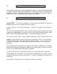
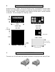
4. 4.1 CONNECTOR WIRING INFORMATION CONNECTOR LOCATION The connectors are the screw terminals that plug into the mating jack mounted on the printed circuit board. P3 is either a 6 conductor phone plug for RS-232 and RS-485 or a 30 pin, mass termination, edge connector for parallel BCD. J2 J1 1 1 J3 J5 J4 1 2 1 6 A 1 1 6 B 6 6 1 3 6 30 4.
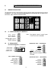
4.4 J 2 - DUAL SETPOINT CONTROLLER RELAY OUTPUTS ALARM 1 - N/O CONTACT ALARM 1 - N/C CONTACT ALARM 1 COMMON 1 2 3 ALARM 2 - N/O CONTACT ALARM 2 - N/C CONTACT ALARM 2 COMMON 4 5 6 SOLID STATE RELAY OUTPUTS Switching AC 125Vac @120 ma max. ALARM ALARM ALARM ALARM ALARM ALARM 1 1 1 2 2 2 - SOURCE 1 - SOURCE 2 DRAIN - SOURCE 1 - SOURCE 2 DRAIN 1 2 3 4 5 6 AC AC AC AC * SOLID STATE RELAY OUTPUTS Switching DC 125Vdc @240 ma max. SOLID STATE RELAY OUTPUTS Switching DC 125Vdc @120 ma max.
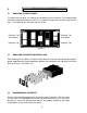
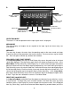
5. 5.1 MECHANICAL ASSEMBLY REMOVING THE REAR PANEL To remove the rear panel, first remove any connectors that are installed. Press down on both rear panel retaining tab releases (see Fig. 5.1) and pull the top of the rear panel away from the case. The bottom of the rear panel will now lift out. Retaining Tab and Release Retaining Tab and Release Retaining Tab Retaining Tab Figure 5.1 5.
6. PANEL MOUNTING Ensure the O-ring is in place. Turn the two mounting screws counterclockwise until the space between the mounting pawl and the bezel is greater than the panel thickness. Insert the meter in the panel cutout. Turn the mounting screws clockwise until the meter is securely mounted in the panel. Do not overtighten the mounting screws. 48mm (1.89in) 96mm (3.78in) 4mm (0.157in) J1 J2 J3 J4 FRONT VIEW REAR VIEW TOP VIEW SIDE VIEW J5 Mounting Pawl 102mm (4.
8. OPERATING THE METER ALARM 2 STATUS INDICATOR ALARM 1 STATUS INDICATOR DISPLAYED ITEM INDICATOR ALARM KEY (REVERSE MENU) MENU KEY PEAK DISPLAY KEY ( DIGIT SELECT ) Figure 8.1 DISPLAYED ITEM / RESET KEY ( VALUE SELECT ) OPERATING MODE The meter is in normal operation and the input signal value is displayed. MENU MODE The meter display and outputs do not respond to the input signal and alarm relays are deenergized.
meter is configured to display more than 1 item), display item #2 is displayed and the displayed item indicator lights. Repeating this selects display item #3 and displayed item indicator flashes. In the Menu Mode or Alarm Mode, the Value Select Key ( Reset Key) sets the value of the flashing digit. Each time the key is pressed, the value increases by one. Holding the key down causes the digit to automatically step through the numbers.
10. SETUP MENU MENU KEY VALUE SELECT KEY DIGIT SELECT KEY DUAL CHANNEL SIGNAL CONDITIONER InPut Input signal type rAtE Frequency or rate Note: (I1), (I2), and (I3) are display items 1, 2, and 3. The value that is displayed may be selected via front panel pushbutton.
DIGIT SELECT KEY MENU KEY VALUE SELECT KEY DUAL CHANNEL SIGNAL CONDITIONER (CONT'D) InPut Input signal type (cont"d) PEriod Period (cont'd) Note: (I1), (I2), and (I3) are display items 1, 2, and 3. The value that is displayed may be selected via front panel pushbutton. Basic counter: A b, A Only Extended counter: All items shown totAL Total Note: To count down, use negative scale factor.
MENU KEY VALUE SELECT KEY DIGIT SELECT KEY DUAL CHANNEL SIGNAL CONDITIONER InPut Input signal type (cont'd) totAL Total (cont'd) Note: Use A-B for up/down counting where input A is the up counts and input B is the down counts. Basic counter: A b, A Only Extended counter: All items shown A - b calculates total for input A (I2), total for input B (I3), and difference of both inputs (I1) A .
DIGIT SELECT KEY MENU KEY VALUE SELECT KEY VOLTAGE-TO-FREQUENCY CONVERTER InPut Input signal type Note: (I1), (I2), and (I3) are display items 1, 2, and 3. The value that is displayed may be selected via front panel pushbutton.
MENU KEY SEtuP Meter Setup (cont'd) VALUE SELECT KEY DIGIT SELECT KEY 00000 Connector inputs (cont'd) Low input = true ConFIG Meter configuration 8 A: Hold B: Ext.
MENU KEY DIGIT SELECT KEY VALUE SELECT KEY dSPYno Item to be displayed at power on. 1 Enter display item # 1 Display item 1 2 Display item 2 3 Display item 3 PULSES Number of pulses per zero (Quadrature only) 00000 00000 00000 00000 00000 Enter number of pulses Select 0 through 9 for flashing digit. GAtE t Gate time (If not Batch) 199.99 Select value from .01 to 199.99 seconds Select 0 through flashing digit. 9 for dSPY t Relay output time ( Batch only ) 199.99 Select value from .01 to 199.
MENU KEY DIGIT SELECT KEY VALUE SELECT KEY 00000 Peak value 0 Unfiltered peak value 1 Filtered peak value 00000 Adaptive filter threshold 0 Low adaptive threshold 1 High adaptive threshold 00000 Filter time constant 0 1 2 3 4 5 6 7 00 Channel A input 0 Positive slope 1 Negative slope 00 Channel B input 0 Positive slope 1 Negative slope dEc.Pt1 Decimal point selection 1.11111 11.1111 111.111 1111.11 11111.1 111111. Use value select key to select decimal point dEc.
MENU KEY DIGIT SELECT KEY VALUE SELECT KEY 0000.00 0000.00 0000.00 0000.00 0000.00 0000.00 Select 0 through 9 for flashing digit. Decimal point fixed by DecPt1. 0.00000 0.00000 0.00000 0.00000 0.00000 0.00000 Scale factor 0.00001 to 100000 Multiplier Select 0 through 9 for flashing digit. Decimal point fixed. Select scale factor multiplier OFFSt2 Offset or Zero Value 0000.00 0000.00 0000.00 0000.00 0000.00 0000.00 Select 0 through 9 for flashing digit. Decimal point fixed by DecPt1.
MENU KEY SourcE Source of alarm operation (only enabled if relay output installed) ALSEt Alarm Operation Setup (only enabled if relay output installed) DIGIT SELECT KEY VALUE SELECT KEY 00 Compare Alarm 1 to: 0 1 2 3 Filtered item Item 1 Item 2 Item 3 00 Compare Alarm 2 to: 0 1 2 3 Filtered item Item 1 Item 2 Item 3 00000 Relay output status when alarm active (On or off) 0 1 2 3 relay 1 on, relay2 on relay 1 off, relay2 on relay 1 on, relay2 off relay 1 off, relay2 off 00000 Relay output statu
MENU KEY ALSEt Alarm Operation Setup (cont'd) dEUtn1 Amount of deviation or hysteresis - Alarm 1 (only enabled if relay or open collector output installed) dEUtn2 Amount of deviation or hysteresis - Alarm 2 (only enabled if relay or open collector output installed) An Set Setup of analog output (only enabled if analog output installed) An Lo Display value for 0 voltage or current output DIGIT SELECT KEY VALUE SELECT KEY 00000 Select to operate as band deviation alarms or as hysteresis around the setpo
MENU KEY DIGIT SELECT KEY VALUE SELECT KEY An Hi Display value for 10 volts or 20 ma output 0000.00 0000.00 0000.00 0000.00 0000.00 0000.00 Select 0 through 9 for flashing digit. Decimal point location fixed by dEC.Pt selection.
MENU KEY DIGIT SELECT KEY VALUE SELECT KEY Ser 3 Serial interface setup 00000 RS485 full or half duplex 0 Full duplex 1 Half duplex (only enabled if communications board installed) 00000 Meter recognition character 0 " * " character 1 Custom character 00000 RS232 RTS type 0 Nonlatching RTS 1 Latching RTS 00000 Carriage return (and LF, if selected) 0 Only at end of all items 1 At end of each item (If alarm, only at end) 00000 Data sent via communications (if BCD, only 1 item allowed 0 1 2 3 4 5
MENU KEY Loc 2 Lockout of Menu Items (Lockout jumper must be removed to access Loc 1, 2, 3, 4. See Figure 9.1) Loc 3 Lockout of Menu Items (Lockout jumper must be removed to access Loc 1, 2, 3, 4. See Figure 9.1) Loc 4 Lockout of Menu Items (Lockout jumper must be removed to access Loc 1, 2, 3, 4. See Figure 9.
11. 11.1 DUAL CHANNEL SIGNAL CONDITIONER SETTING JUMPERS FOR INPUT SIGNAL LEVELS a c B4 b a B3 Channel B c b B0 a A3 A4 b a B2 a b B1 A1 b a b a b a a A2 A0 b Channel A b a b Minimum High and Low Input Signal Levels The jumper settings for Channel A (A2 & A3) and Channel B (B2 & B3) are selected depending on the input amplitude. The input signal voltage must exceed the high and low threshold per the following table or the meter will not operate properly.
11.3 MODES OF OPERATION Input Arm Signal Gate Internal Clk The measurement starts with an input signal transition in one direction and ends, after the expiration of the selected gate time, with the next input signal transition in the same direction such that the conversion time or period is measured over an integral number of input cycles. The internal Start signal ARMS the gate circuit so that the next input signal transition actually OPENS the gate.
Relay #3 energizes and the cycle repeats. As an option, the cycle can be reset from an external signal FUNCTION RESET. The GATETIME is not used and Relay #1 remains de-energized until the FUNCTION RESET external input is grounded for a minimum of 3.33 mS. Sometime during that period, the Batch Total is reset and Relay #1 is energized. The Batch Total is displayed as Item #1 and may be configured to count up from 0 to the preset value, or to count down from the preset value to 0.
RATE AxB is the same as Rate A+B except that A is multiplied by B. RATE A/B (Ratio) is the same as Rate A+B except that A is divided by B. Rate A and B may be scaled such that the ratio of A/B is 1. When the value of B increases the ratio is a number less than 1 and when it decreases the number is greater than 1. RATE A/B-1 (Draw) is the same as Rate A/B (Ratio) except that 1 is subtracted from the ratio to give a zero value when the ratio of the 2 inputs is 1.
TOTAL A-B UPDN is the same as Total A, Total B except that Total A is displayed as item 2, Total B is displayed as item 3 and the difference of A minus B is displayed as item 1. Decimal point 1 applies to both A and B and decimal point 2 applies to the sum of A and B. The resolution of the sum is determined by setting the multiplier (Resolution) from .00001 to 100000. BURST measures the frequency of a burst of pulses from channel A as item 2, and total number of bursts as item 1.
is a number less than 1 and when it decreases the number is greater than 1. 11.7 TIME INTERVAL TIME INTERVAL A TO B measures time between an input on channel A and an input on channel B. Time measurement starts when a pulse is applied to channel A (positive edge if slope A is 0, negative edge if slope A is 1) and the measurement ends when a pulse is received on channel B (positive edge if slope B is 0, negative edge if slope B is 1).
12. 12.1 V - TO - F SIGNAL CONDITIONER SETTING JUMPERS FOR INPUT SIGNAL LEVELS A1 b a Input Range 0 to 10V 0 to 1mA 4 to 20mA Jumper Position A1 None a b 12.2 RATE Rate A is the voltage or current input converted to a frequency output of 0 to 100kHz. The period of the frequency is measured and converted to a rate by 1/period and applying Scale1 and Offset1.
the preset value, or to count down from the preset value to 0. The preset value is placed in Setpoint 1 and the Batch Total is the total with Scale1 and decimal point1 applied. In the Batch mode, Scale1 is set to a positive value to count up and a negative value to count down. Offset1 is set to zero when counting up and to the preset value when counting down. The Grand Total is kept as Item #2.
13. 13.
13.2 QUADRATURE DECODING The quadrature decoder board generates up(+) and down(-) counts that are arithmetically totalized on the main counter board and then displayed. The decoder board has input circuitry that may be jumpered for either single-ended input signals or balanced line driver signals. It will accept the normal A & B quadrature signals and, if present, a zero index signal.
The zero index channel contains the same digital filtering that is provided for the A & B channels. It contains a Polarity jumper that allows selection of either a positive or negative zero index signal. It also contains two Control inputs, C1 and C2 that control the ANDing of the zero index signal with the Channel A and Channel B signals. See “Zero Index Setup” below. The Item indicator light (center right) may be used to determine the location of the Zero Index.
13.3 ZERO INDEX SETUP The relationship between the zero index correction signal and the Channels A & B signals varies with different encoder model numbers and different manufacturers. To accommodate this variation, the Quadrature board has control jumpers and selectable outputs that provide ANDing of the zero index signal with all possible combinations of the Channel A & B signals. Consider a typical encoder model that produces the waveforms shown below. Assume X4 counting is selected.
between counting up and counting down. There are 2 control signals, C1 and C2, and 3 outputs, ZI, ZIX and ZIY that may be jumpered to provide 8 selections of ANDed signals or the zero index signal without ANDing.
counter=0 and the correction=0. The position of the encoder when the counter is reset is not critical. 8. Rotate the optical encoder past the zero index point to set the internal correction. 9. Return to the desired zero mechanical position and verify a zero reading. This completes the procedure. If the encoder is rotated back to mechanical zero, it should read zero.
used here, remove jumper c of E10 that was placed for the test in A. above. C. From the manufacture's specifications for the encoder, determine the number of cycles per revolution. Multiply this by 1, 2, or 4 depending on the selection of X1, X2 or X4 counting and multiply that result by the counter scale factor. Put the final result in the counter Menu item, PULSES. 5. Finally, follow the procedure outlined above under the heading titled, MECHANICAL ZERO. 13.
Models MX-15, MX-21 CCW rotation A Channel B Channel Zero Index (gated) Models E20, E11, E15, CMX216, MOD900 CW rotation A Channel B Channel Zero Index BOURNS EN Series A Channel B Channel Zero Index COMPUTER OPTICAL PRODUCTS Models CP-350, CP-360, CP-370, CP-850, CP-870 CW rotation viewing shaft end A Channel B Channel Zero Index 90-270 deg ENCODER PRODUCTS CO.
A Channel B Channel Zero Index GRAYHILL CW rotation A Channel B Channel No zero index OAK-GRIGSBY CW rotation A Channel B Channel No zero index 13.7 QUADRATURE RATE Rate and direction may also be displayed using an extended version of the counter. Using quadrature to determine rate not only has the advantage of displaying direction but also eliminates errors due to vibration and jitter that cause erroneous readings in standard rate meters. The meter uses A-B to display quadrature rate.
14. DUAL ALARM OUTPUTS 14. 1 OPERATING MODE MENU SELECTION When setting up the meter, it may be necessary to enable some of the menu items. See Section 10 for further information. MENU KEY Press the key until SourcE (Source of Alarm signal) is displayed. See Section 10, ALSEt for detailed selection information for Digits 1 through 6. Press the key until ALSEt (Alarm setup) is displayed. See Section 9, ALSEt for detailed selection information for Digits 1 through 6.
in Deviation. In the Hysteresis mode, the Alarm energizes above (or below) the setpoint by the amount entered in deviation and deenergizes below (or above) the setpoint by the same amount 14. 3 VIEWING AND CHANGING SETPOINTS When viewing or changing the setpoint values, it is not necessary to enter the setup menu. This allows the meter to continue conversions and provide outputs when the setpoints are displayed.
15. RS-232 AND RS-485 INTERFACE 15. 1 JUMPER SELECTIONS RS232 Interface Jumper g - installed for normal operation Jumper h - installed when used as a slave display with the RS232 output of another Laureate meter. Jumper j - provides a pull-up resistor on the RTS line. g h j Note: The board is shipped standard with jumpers g and j installed RS232 RS485 Interface Note: Bias jumpers b and e must be installed on board for proper operation.
15. 2 OPERATING MODE MENU SELECTION The following menu items are accessible only with an RS-232 or RS-485 option installed and appropriate lockouts enabled. See Section 9 for further information. MENU KEY DIGIT SELECT KEY 1 2 Press the key until SEr 1 (Serial interface setup 1) is displayed. Press the key until SEr 2 (Serial interface setup 2) is displayed. 3 4 5 1 2 3 4 5 to select value for Press to display status. Press flashing digit Press again to select digit.
16. ANALOG OUTPUT The analog output option provides a 0 to 20mA and a 0 to 10Vdc linear signal derived from the displayed reading. The low signal output and high signal output may be set to equal any displayed value. Although both outputs are available, only one is calibrated to specifications. The other output is accurate to +/-1% of the displayed value typical (2%max). To select which output is calibrated, install jumpers per Section 19. 1. 16.
17. PARALLEL BCD OUTPUT 17. 1 OPERATING MODE MENU SELECTION The following menu items are accessible only with a BCD option installed and appropriate lockouts enabled. See Section 10 for further information. MENU KEY Press the key until SEr 1 (Serial interface setup 1) is displayed. DIGIT SELECT KEY 1 2 3 4 5 Press to display status. Press again to select digit. Selected digit will flash.
18. 5, 10 AND 24 VDC EXCITATION OUTPUTS b c d e f h g a Figure 18. 1 - Power Supply Jumper ' a ' Jumper ' h ' Jumper ' g ' - Front panel menu lockout (see Section 9.1) External Input B at output connector P1 - 4 +5V at output connector P1 - 4 18. 1 SELECTION OF 5, 10 OR 24VDC OUTPUT Voltage Output Jumper Locations 5 Vdc 10 Vdc 24 Vdc b, d and e b, d and f c b d b d e 5 Vdc f 10 Vdc c 24 Vdc Note: The excitation power supply is floating with respect to meter ground.
19. 19.1 DIGITAL INPUTS FUNCTION OF DIGITAL INPUTS Meter Reset Logical 0 - The microcomputer reads and resets the meter to the values stored in nonvolatile memory. If totals are saved on power down, totals are reset to the saved value, otherwise totals are set to zero or to the offset value if offset is not zero.
20. CALIBRATION All ranges of the meter have been digitally calibrated at the factory prior to shipment. The calibration equipment is certified to NIST standards. Calibration constants are stored in nonvolatile memory in EEPROM on the main board , the V-to-Fsignal conditioner and on the analog output board. The crystal on the main board is calibrated via the menu item "calib". Using an accurate, known frequency, the meter is calibrated by entering the error of the in parts per million.
Isolation ................................................................channel A & channel B share common ground Selectable Low Pass Filter ...................................................................................................1600 Hz Hysteresis ..................................................................................selectable from 15 mV to 2.2 Vp-p Trigger level .................................................................................... selectable from 0 V to +/-1.
Alarm Status Indicators Type ..........................................................................................................................2 red LED lamps Setup ......................................................................... either indicator may be set to light when the output is on or off or may be disabled Relay Output Contact Rating .............................................................................. 10 A @ 240 Vac, 8 A @ 24 Vdc Safety Certification........................
BCD OUTPUT OPTION Isolation ..................................................Safety-rated to 250Vac, 4.2kVp per High Voltage Test Power ........................................................................................................... supplied by basic meter Type ...............................................................................................................3-state, stored, parallel Signal Levels .......................................................................................
EEPROM via the serial communications. Up to 240 data points may be entered into a test file with one set of values equivalent to input signal and the second set of values the desired display at that input. Deviation Either alarm may operate in the deviation mode. In the menu item "deviation", a value is entered equivalent to the amount above and below the setpoint at which the alarm operates.
Phase Angle In this mode, the meter determines the phase angle between the signals on Channel A and Channel B. The phase angle is measured from 0 to 360 degrees Pulses The menu item pulses is used to set the number of pulses generated by a quadrature encoder for each zero index pulse. The setting is equal to the number of pulses per revolution of the encoder (times 2 or 4 if the count by 2 or 4 is selected on the signal conditioner) times the scale factor.
WARRANTY Laurel Electronics Inc. warrants its products against defects in materials or workmanship for a period of one year from the date of purchase. In the event of a defect during the warranty period, the unit should be returned, freight prepaid (and all duties and taxes) by the Buyer, to the authorized Laurel distributor where the unit was purchased. The distributor, at its option, will repair or replace the defective unit.