SERIAL INPUT METER & REMOTE DISPLAY LAUREATE SERIES 2 OWNERS MANUAL Now with Ethernet LAUREL Electronics Inc. 3183-G Airway Ave, Costa Mesa, CA, 92626, USA Tel: (714) 434-6131 • Fax: (714) 434-3766 • Website: www.laurels.
1. ORDERING GUIDE Configure a model number in this format: L5002, CBL01 L......... .................... Serial input meter Includes screw terminal connectors. Digital Interface 0 ....................................................... None 1 .....................................................RS232 2 .....................................................RS485 4 .......................................RS485-Modbus 5 ........................................................ USB 6 ........................
. PRODUCT INTRODUCTION Our Serial Input Meter (or remote display) accepts serial data from computers, programmable controllers, instruments or other devices to provide a six-digit numeric display from -999,999 to +999,999. It can also provide relay closures and analog outputs based on the received serial data. Its appearance matches that of our 1/8 DIN digital panel meters, counters and timers. The Serial Input Meter is a 6-digit counter without a signal conditioner board.
. RECEIVING & UPACKING Your serial input meter was carefully tested and inspected prior to shipment. Should the meter be damaged in shipment, notify the freight carrier immediately. In the event the meter is not configured as ordered or the unit is inoperable, return it to the place of purchase for repair or replacement. Please include a detailed description of the problem. 5.
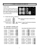
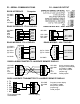
6. CONNECTOR WIRING INFORMATION CONNECTORS Connectors for signal and power are U/L rated screw-clamp terminal blocks that plug into mating jacks on the printed circuit board. Communication connectors are a single RJ11 plug for RS232, dual RJ11 plugs for RS485, and dual RJ45 plugs for RS485-Modbus.
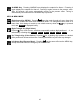
P3 - SERIAL COMMUNICATIONS RS232 INTERFACE ISO GND ISO GND RX TX RTS ISO GND 6 5 4 3 2 1 P4 - ANALOG OUTPUT Computer GND TX RX RTS RS485 INTERFACE - FULL DUPLEX ISO GND BRX ARX ATX BTX ISO GND RS485 INTERFACE - HALF DUPLEX ISO GND GND BTX ATX ARX BRX GND 6 5 4 3 2 1 ATX / ARX BTX / BRX ISO GND RS485-MODBUS - FULL DUPLEX (A') RXD0 (B') RXD1 + 1 2 3 4 5 6 7 8 (B) TXD1 * (A) TXD0 ISO GND GND 6 5 4 3 2 1 ATX / ARX BTX / BRX GND RS485-MODBUS - HALF DUPLEX TXD0 TXD1 RXD1 RXD0 (B) TX / RXD1 (A) TX
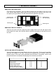
. MECHANICAL ASSEMBLY REMOVING THE REAR PANEL First remove any connectors. Use one hand to press in the two sides of the rear of the case, and the other hand to press down the two protruding tab releases at the top of the rear panel (see figure below). This will unhook the rear panel from the case.
Note: Corresponding main board and option board connectors have the same number of electrical lines. When an option board is correctly installed, the top and bottom edges of the main board and option board are aligned. REASSEMBLING YOUR METER Slide the electronics assembly into the case until the display board is seated flush against the front overlay. Insert the bottom tabs of the rear panel into the case, then carefully align the board connectors with the openings in the rear panel.
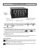
8. FRONT PANEL SETUP KEYS Counter Front Panel There are four front panel keys, which change function for the Run Mode and Menu Mode, effectively becoming eight keys. The keys are labeled with alphanumeric captions (MENU, PEAK, RESET, ALARMS) for the Run Mode and with symbols ( right arrow, right left arrow) for the Menu Mode.
ALARMS Key. Pressing ALARMS once displays the setpoint for Alarm 1. Pressing it again displays the setpoint for Alarm 2. Pressing it again returns to the present value. After 30 seconds, the meter automatically returns to the present value. Timing is automatically reset whenever the ALARMS key is pressed. KEYS IN MENU MODE Right Arrow Key (MENU). Pressing steps the meter through all menu items that have been enabled and then back to the Run Mode.
9. ENABLING & LOCKING OUT MENU ITEMS For security reasons and ease of operation, any and all menu items may be disabled or "locked out" so that they are no longer directly accessible from the front panel. Each function to be enabled is set to "0" and each function to be disabled is set to "1" in menu items Loc 1-4. These menu items can in turn be locked out by installing an internal hardware jumper. With the jumper installed, the operator only has access to enabled menu items.
10. SERIAL INPUT METER / REMOTE DISPLAY CONFIGURATION Serial input meter / remote display operation of a counter utilizes a Basic counter main board and a serial interface board. A signal conditioner board is not required, but will not interfere with remote display operation if installed. A serial communications board is required. This can be any of the following: RS232 board, USB Board, USB-to-RS485 board, RS485 board, Modbus RS485 board, Basic Ethernet board, Etherned-to-RS485 converter board.
SELECTED FRONT PANEL SETUP ITEMS FOR SERIAL INPUT METER (not consecutive) If the MENU Press Menu key does not work, see Section 9 “Enabling & Locking Out Menu Items.” Press Digit Select Key Press Value Select Key SEtuP Setup _000_0 Control inputs 1 and 2 F 1 = Tare, 2 = Tare enable Control input 2 must be at 0V or grounded for Tare to operate. ConFiG Configuration __0000 Display mode 6 7 8 9 A B C .ti_Out. Time-out _000.00 _000.00 _000.
11. SERIAL COMMUNICATIONS OPTIONS A serial communications board is required for serial input meter / remote display operation. The communications board is connected to the meter main board at plug position P13 (middle position). Available boards are RS232, RS485 (with dual RJ11 connectors), RS485 Modbus (with dual RJ45 connectors), USB, USB-to-RS485 converter, Ethernet, and Ethernet-to-RS485 converter.
USB Board No jumpers required. Basic Ethernet Board No jumpers needed. RS232 Board e - Normal operation. f - Slave display to RS232 from another meter. g - Pull-up resistor on RTS line. Note: Board is shipped with jumpers e and g installed RS485 Board, Full Duplex Operation * b & d - Installed on last meter in long cable run. RS485 Board, Half Duplex * a & c - Installed for half duplex operation. d - Installed on last meter in line with long cable runs.
KEYSTROKES FOR SETUP key does not work, see Section 9 “Enabling & Locking Out Menu Items.” If the MENU Press Menu Key .Ser 1. Serial Setup 1. Press until Ser 1 is displayed. Fixed Parameters No parity 8 data bits 1 stop bit .Ser 2. Serial Setup 2 .Ser 3. Serial Setup 3. Press Digit Select Key Press Value Select Key ___000 Output filtering 0 Send unfiltered signal 1 Send filtered signal ___000U Baud rate 0 1 2 3 300 baud 600 baud 1200 baud 2400 baud ___000U Digital output rate. rr = reading rate.
12. DUAL & QUAD RELAY OUTPUT OPTIONS An optional relay board may be installed in the meter main board at plug position P2, adjacent to the power supply board. Four board versions are available: 2 or 4 relays, contact or solid state. Once installed, the relay board is recognized by the meter software or PC-based Instrument Setup software, which will bring up the appropriate menu items for the type of board. These menu items will not be brought up if a relay board is not detected.
KEYSTROKES FOR SETUP key does not work, see Section 9 “Enabling & Locking Out Menu Items.” If the MENU Press Menu SourcE Source to compare to setpoint Press Digit Select Key Press Value Select Key 0000 Setpoint 1: 3 Must be set to Item #3. 0000 Setpoint 2: 3 Must be set to Item #3. 0000 Setpoint 3: 3 Must be set to Item #3. 0000 Setpoint 4: 3 Must be set to Item #3. AL SEt 00000 Alarm Setup Relay state when alarm is for relays 1 & 2 active if detected.
Press Menu Press Digit Select Key Press Value Select Key 0 1 2 3 Relay 3 on Relay 3 off Relay 3 on Relay 3 off Relay 4 on Relay 4 on Relay 4 off Relay 4 off 00000 Alarm latching or nonlatching (auto reset). (see Glossary) 0 1 2 3 Alarm 3 auto reset Alarm 3 latching Alarm 3 auto reset Alarm 3 latching Alarm 4 auto reset Alarm 4 auto reset Alarm 4 latching Alarm 4 latching 00000 Alarm operates at and above setpoint (active high) or at and below setpoint (active low).
13. SINGLE & DUAL ANALOG OUTPUT OPTIONS Two versions of an analog board may be installed in the meter at rear panel jack position J4, adjacent to the signal conditioner board. Once installed, this board is recognized by the meter, which will bring up the appropriate menu items for it. These will not be brought up if an analog output board is not installed.
KEYSTROKES FOR SETUP OF DUAL ANALOG OUTPUT BOARD If the MENU key does not work, see Section 9 “Enabling & Locking Out Menu Items.” Press Menu Key Press Digit Select Key Press Value Select Key 0000 Scaling of analog output 2 0 0-20 mA current output 1 0-10V voltage output 2 4-20 mA current output 0000 Source of analog output 2 3 Must be set to Item #3.
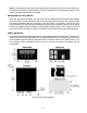
14. INSTRUMENT SETUP VIA PC OVERVIEW Our serial input meters are easily programmed using a PC with an RS232 port and Instrument Setup (IS) Software, which provides a graphical user interface. The software allows uploading, editing, downloading and saving of setup data, execution of commands under computer control, listing, plotting and graphing of data, and computer prompted calibration. USING INSTRUMENT SETUP SOFTWARE Use a 4-wire RS232 cable (P/N CBL01) to connect your meter to the COM port of your PC.
In the Establish Communications screen, select your Com Port and 9600 as the Baud Rate. You will be able to change your protocol and baud rate later under the Communication setup tab. Click on Establish, and the two fields at the bottom of the screen should turn green. Click on the Main Menu button. From the Main Menu, click on Counter => Get Setup to retrieve (or get) the existing setup data from your remote display.
Click on Counter => Get Setup to retrieve the current setup information from your counter, then on View => Setup, which will take you to the Input+Display tab. Use this screen to set up Display Type, Control Inputs and Time Out. For Time Out, enter the number of seconds that a serial reading will be displayed in the absence of a new serial input, after which ti-Out will be displayed. If timeout is set to 000.00, the display will persist indefinitely in the absence of a new input.
Input+Scaling tab. Works only with the Custom ASCII protocol, not the Modbus protocol, since a meter cannot listen to commands while in the Rmt Dsply C display type. Executing a Main Menu > Counter > Put Setup command downloads the setup information into the meter, including the Rmt Dsply C display mode if selected. Do not execute a Main Menu > Counter > Get Setup command if you have placed the meter into the Rmt Dsply C mode, since normal meter communications cannot occur in that mode.
Click on the Relay Alarms tab to set up your meter’s two or four optional relays. The same digital source is used for all relays and must be set to Item 3 under Alarm Source. A separate Setpoint and a Hysteresis band or Deviation band can be set up for each relay. The relays will respond to your digital entries without decimal point. For help with any selectable item, select that item with your cursor and press the F1 key. This will bring up a help window like the one shown.
Click on the Communication tab to view the communication parameters that you used to establish default communications with your transmitter. You can reselect Baud Rate, Device Address, Serial Protocol, Full/Half Duplex, even though you may have selected different values to establish initial communications with your PC. You can also define a Custom Recognition Character in lieu of the default *.
Click on the Analog Out tab to scale your meter’s optional single or dual analog outputs. Item 3 must be selected as the Analog Output Source. With dual analog outputs, that same digital source will be used for both outputs, but the outputs can be scaled independently of each other. For each output, select 0-20 mA Current, 0-10V Voltage, or 4-20 mA under Range. Enter the Lo Range Reading which will correspond to the bottom of your analog output (such as 4 mA).
15. SPECIFICATIONS DISPLAY Type ................................................6 LED digits, 7-segment, 14.2mm, plus 4 LED indicators Digit Color ...........................................................................................................Red or green Display Range ......................................................................................... -999999 to +999999 POWER REQUIREMENTS Input Voltage rating (standard) .......................................................
Scaling of Reading for Full Scale Output............................................... -999,999 to +999,999 Isolation rating between signal common and analog output....................................... 250V ac Insulation dielectric strength between signal common and analog output................................ ................................................................................... 3.5 kV ac for 5 sec, 2.3 kV ac for 1 min SERIAL INTERFACE OPTIONS Output Types..................................
16. GLOSSARY OF TERMS Alarm, latched: An alarm which stays actuated until reset. Latched alarms can shut down machinery or a process when an operating limit has been exceeded, or maintain an alarm condition until acknowledged by an operator. Alarm, non-latched: An alarm which changes state automatically when the reading rises above a specified limit and changes back automatically when the reading falls below a limit.
17. WARRANTY Laurel Electronics Inc. warrants its products against defects in materials or workmanship for a period of one year from the date of purchase. In the event of a defect during the warranty period, the unit should be returned, freight prepaid (and all duties and taxes) by the Buyer, to the authorized Laurel distributor where the unit was purchased. The distributor, at its option, will repair or replace the defective unit.