Custom ASCII Protocol SERIAL COMMUNICATIONS MANUAL For Laureate Series 2 Digital Panel Meters, Counters, Timers & L-Series Transmitters Now with Ethernet LAUREL Electronics Inc. 3183-G Airway Ave, Costa Mesa, CA, 92626, USA Tel: (714) 434-6131 Fax: (714) 434-3766 Website: www.laurels.
1. TABLE OF CONTENTS 1. TABLE OF CONTENTS ....................................................................................................... 2 2. INTRODUCTION, CUSTOM ASCII SERIAL PROTOCOL ..................................................... 3 3. SERIAL CONNECTION EXAMPLES.................................................................................... 5 4. JUMPER SETTINGS & FIELD WIRING FOR SERIAL COMMUNICATIONS......................... 7 5. INSTRUMENT SETUP SOFTWARE ....................
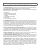
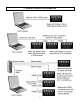
2. INTRODUCTION, CUSTOM ASCII SERIAL PROTOCOL The Custom ASCII Protocol is a simple serial communications protocol which is optimized for use with our programmable digital panel meters, counters, timers and transmitters. Digital panel meters, counters and timers accept an optional serial communications plug-in board, which can be any of the following: • • • • • • • RS232 board RS485 board with dual RJ11 jacks.
USB connection of multiple meters to a PC can be via a USB hub or up to 5 hubs in series. Each USB connection is then automatically assigned a virtual com port number, which can be addressed via software. The USB standard specifies the maximum length of a USB cable as 5 meters (16 ft).
3.
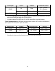
4. JUMPER SETTINGS & FIELD WIRING 1. SAFETY WARNINGS Digital panel meters, counters, timers and transmitters may be powered with AC (mains) from 85-264 Vac or 95-300 Vdc with standard high voltage power, or 12-34V ac or 10-48 Vdc with the low voltage power supply option. To avoid the possibility of electrical shock or damaging short circuits, always unplug the device before opening the case. Please refer to the respective device manuals for full safety information and instruction on how to open the case.
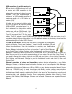
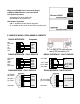
Ethernet-to-RS485 Device Converter Board & USB-to-RS485 Device Converter Board Full Duplex Operation No jumpers for short cable runs. Add b & d for long cable runs. Half Duplex Operation a & c - Installed for half duplex operation. d - Installed on last meter in line with long cable runs. 3.
4.
Serial Signal RS485 RS232 Duplex Jumpers Termination Resistor* Full None E6 a = Transmit E6 c = Receive Half E6 b + d** E6 c Full None None * The termination resistor jumper settings should only be selected if the transmitter is the last device on an RS485 line longer than 200 feet (60 m). ** Or jumper external BTX to BRX and ATX to ARX (same effect as internal jumpers).
5. PROGRAMMING YOUR SERIAL DEVICE OVERVIEW Digital panel meters, counters, timers and transmitters are easily programmed via their serial port using Windows-based Instrument Setup (IS) software, which provides a graphical user interface and is available at no charge. This software allows uploading, editing, downloading and saving of setup data, execution of commands under computer control, listing, plotting and graphing of data, and computer prompted calibration.
6. FRONT PANEL SETUP, SERIAL COMMUNICATIONS 6.1 FRONT PANEL SETUP, DIGITAL PANEL METERS & SCALE METER ONLY Press Menu Select Key .SEr 1. Press until Ser 1 is displayed. Fixed Parameters: - No parity - 8 data bits - 1 stop bit Press Digit Select Key __000 Output filtering 0 Send unfiltered signal 1 Send filtered signal __000U Baud rate 0 1 2 3 4 5 6 300 baud 600 baud 1200 baud 2400 baud 4800 baud 9600 baud 19200 baud 0 1 2 3 4 5 6 7 8 9 60 Hz 0.017 sec 0.28 sec 0.57 sec 1.1 sec 2.3 sec 4.5 sec 9.
Press Menu Select Key .SEr 3. Serial Setup 3 SEr 4. Serial Setup 4 _Addr Modbus Address* Press Digit Select Key Press Value Select Key 00000U RS485 half or full duplex 0 Full duplex 1 Half duplex 00000U Special start & stop char.
6.2 FRONT PANEL SETUP, COUNTERS & TIMERS ONLY Press Menu Select Key . Ser 1. Serial Setup 1. until Press Ser 1 is displayed. Fixed Parameters - No parity - 8 data bits - 1 stop bit . Ser 2. Serial Setup 2 . Ser 3. Serial Setup 3 Press Digit Select Key Press Value Select Key ___000 Output filtering 0 Send unfiltered signal 1 Send filtered signal ___000U Baud rate 0 1 2 3 300 baud 600 baud 1200 baud 2400 baud 4 4800 baud 5 9600 baud 6 19200 baud 0 1 2 3 4 5 6 7 8 9 60 Hz 0.017 sec 0.28 sec 0.
Press Menu Select Key Ser 3. (continued) Ser 4.
7. CUSTOM ASCII COMMUNICATION PROTOCOL 7.1 SERIAL COMMUNICATION FORMAT The Custom ASCII serial communication format for RS232, RS485 and USB is the following: Duplex ...................... Full duplex for RS232 & RS485. Half duplex selectable for RS485. Baud Rate ................. 300, 600, 1200, 2400, 4800, 9600, 19200 selectable by front panel Menu item “Ser 1”, Sub-menu item “Digit 4” for DPM, "Digit 5" for counter. Parity ........................ None Word length .............. 8 data bits Stop bit ....
The Counter and Scale Meter are capable of supplying more than 1 measurement value (or “Item”) with each reading, as selected in “Ser 3”. In the counter, there can be up to 3 Items plus Peak and Valley values, depending on the selected Function. The scale meter can transmit Net, Gross and Peak weight. Values are transmitted in a continuous string with no space between them. If the 5th digit in “Ser 3” is set to 1, the termination characters of and optional appear after each value.
8. CONTINUOUS MODE 8.1 OVERVIEW In the Continuous Operating Mode, measurements are continuously transmitted by the meter or transmitter in a standard data format using printable ASCII characters at a user-selectable rate ranging from 50 or 60 Hz line frequency down to one measurement every 72 seconds. This data may be received by a remote display at a distant location, by a printer for data logging purposes, or by a host computer for data analysis or system control.
Baud Rate Time 1 Item Min Gate Time 2 Items Min Gate Time 3 Items Min Gate Time 4 Items Min Gate 300 600 1200 2400 4800 9600 19200 0.37s 0.18s 0.09s 0.05s 0.02s 0.01s 0.01s 0.34s 0.15s 0.06s 0.02s 0.01s 0.01s 0.01s 0.70s 0.35s 0.18s 0.09s 0.04s 0.02s 0.01s 0.67s 0.32s 0.15s 0.06s 0.01s 0.01s 0.01s 10.03s 0.52s 0.26s 0.13s 0.07s 0.03s 0.02s 1.00s 0.49s 0.23s 0.10s 0.04s 0.01s 0.01s 1.37s 0.68s 0.34s 0.17s 0.09s 0.04s 0.01s 1.34s 0.65s 0.31s 0.14s 0.06s 0.01s 0.
9. COMMAND MODE 9.1 OVERVIEW In the Command Mode, the device does not send any data automatically, but responds to commands received from a host computer. These commands can be: To transmit the latest, peak, or valley measurement. To reset the meter completely or just the peak and valley values and latched alarms. To display a value sent from the computer. To transmit present setup parameters. To receive new setup parameters. To monitor or alter data in selected memory locations of the meter.
Meter # Meter SER 2 Digit 5(6) Serial Comm Address Code 1 2 3 4 5 6 7 8 9 10 11 12 13 14 15 1 2 3 4 5 6 7 8 9 A B C D E F 1 2 3 4 5 6 7 8 9 A B C D E F Meter # Meter SER 2 Digit 5(6) Serial Comm Address Code 16 17 18 19 20 21 22 23 24 25 26 27 28 29 30 31 0. 1. 2. 3. 4. 5. 6. 7. 8. 9. A. B. C. D. E. F. G H I J K L M N O P Q R S T U V CHARS 3 & 4 - COMMANDS AND SUBCOMMANDS The examples below use a default address of 1 following the “*“.
REQUEST COUNTER VALUES All active items 1, 2 or 3 Item 1 Item 2 Item 3 Peak Displayed item Valley All active items + Peak + Valley *1B0 *1B1 *1B2 *1B3 *1B4 *1B5 *1B6 *1B7 RESET FUNCTIONS, DPM & SCALE METER Cold reset Latched alarms reset Peak value reset Remote display reset External Input B true External Input B false External Input A true External Input A false Valley reset Tare function Tare reset *1C0 Reads NVMEM into RAM locations after RAM is zeroed.
CHARACTER 3: Command character: G F R Q X W Read bytes from RAM Memory Write bytes to RAM Memory (DPM and Scale meter only) Read bytes from Upper RAM Memory Write bytes to Upper RAM Memory Read words from Non-Volatile Memory Write words to Non-Volatile Memory CHARACTER 4: Number of bytes (G, F, R, Q) or words (X, W) Code # 1=1 2=2 3=3 4=4 5=5 6=6 7=7 8=8 9=9 A = 10 B = 11 C = 12 D = 13 E = 14 F = 15 G = 16 H = 17 I = 18 J = 19 K = 20 L = 21 M = 22 N = 23 O = 24 P = 25 Q = 26 R = 27 S = 28 T = 29 U = 30
The number of bytes n consists of a single code character representing values from 1 to 30 as shown above under CHARACTER 4. The most significant address aa consists of 2 hex characters as shown below under RAM MEMORY ADDRESSES AND DATA DEFINITIONS. GENERAL, READING AND WRITING NONVOLATILE MEMORY DATA Nonvolatile data is read and written as a continuous string of words consisting of 2 bytes or 4 hex characters (0-9,A-F) per word.
A total of 11 characters plus a CR must be included and sent as ASCII characters. Those in quotes below are included as shown. The other symbols represent a range of characters except for CR which is the ASCII character “0D”.
MODE 2: DPM with Signal Conditioner Card and in Remote Display Mode SETUP (left digit) = 1 Remote Display mode The baud rate must be set the same as the source which may be a PC Controller or another DPM. The format is the Slave Format. This is the same as MODE 1 above but without the Command Identifier “*”, the address #, and the Command letter “H”. This is the same format that data is transmitted from a DPM in the Continuous mode.
Remote Display Only – No Normal Readings 6 7 8 9 A B C Addressable remote display Single value remote display 1st value of value sequence 2nd value of value sequence 3rd value of value sequence 4th value of value sequence Programmed to select specific data from a data string Addressable Commands H, K or L commands 1 value only 1-4 sequential Values 2-4 sequential Values 3-4 sequential Values 4 sequential Values 1 value only The addressable commands of Modes 0-6 can display remote data on one or more Coun
Mode 7 is not addressable, and data representing a value to be displayed is received in a pointto-point connection. In addition to being displayed, that value is put into Item 3, where it may be selected for Alarm comparisons and/or for Analog Output. If a Coded Alarm character is included, it overrides the internal alarm comparisons. Modes 8-11 are able to extract one value of data from a sequence of values, and display that particular value only.
S = Sign of value, space (or +) for positive, - for negative value. Sign is optional in display modes 0-7, required in 8-11. D = Digit from 0 to 9. Number of digits may be 1-6 in display modes 0-7, but must be 6 in 8-11. P = Power of 10. 0-9, A-F where A-F represents 10-15 A = Optional Alarm Character as defined in section 2.1 = Carriage return character = Optional line feed character (ignored) These basic Command formats are used when the Remote Display Counter is in display modes 0 - 6.
10. APPENDIX A: DPM MEMORY ADDRESSES AND DATA DEFINITIONS 10.1 DPM 1-BYTE RAM MEMORY DATA (L) = Lower memory, (U) = Upper memory. The bit assignments below constitute an 8-bit binary number, which needs to be converted to Hex using a program such a Scientific Calculator under MS Windows Accessories. To change an Item in DPM RAM Memory, write the converted Hex value to the Hex Address shown in the left column. To change an Item in Nonvolatile Memory, go to table 10.
69 (L) Serial Cnfg3 Bit 7 6 5 4 3 2 0 0 0 0 1 1 0 1 0 1 0 1 0 1 1 0 0 0 Send Reading 0 1 Send Peak 1 0 Send Valley 1 1 Send Reading + Peak 0 0 Send Reading + Valley 0 1 Send Reading + Peak + Valley or at end of all Items or at end of each Item (if no Alarm character) Non-latching RTS Latching RTS Normal continuous TX Special Start & Stop characters Full duplex Half duplex 35 (L) Decimal Point 01 Byte values in hex 02 (2 hex characters/byte) 03 04 05 06 34 (L) Lockout2 0 =
(L) Serial Cnfg2 Bit 7 6 5 4 3 2 1 0 X X X X X Binary Custom ASCII addr. 0-31 0 Continuous mode 1 Command mode 0 Alarm data not included with rdg. 1 Alarm data included with rdg. 0 No following 1 following 31 (L) Serial Cnfg1 Bit 7 6 5 4 3 2 1 0 Continuous Output Data Rate 60 Hz 50 Hz 0 0 0 0 0.017s 0.02s 0 0 0 1 0.28 0.34 0 0 1 0 0.57 0.68 0 0 1 1 1.1 1.4 0 1 0 0 2.3 2.7 0 1 0 1 4.5 5.4 0 1 1 0 9.1 10.9 0 1 1 1 18.1 21.8 1 0 0 0 36.3 43.
2F (L) Filter Bit 7 6 5 4 3 2 1 0 0 0 0 0 Auto Filter 0 0 0 1 Batch (16 samples) filter Time constant 60 Hz 50 Hz 0 0 1 0 Moving average 0.07 s 0.085 s 0 0 1 1 Moving average 0.14 0.17 0 1 0 0 Moving average 0.28 0.34 0 1 0 1 Moving average 0.57 0.68 0 1 1 0 Moving average 1.13 1.36 0 1 1 1 Moving average 2.27 2.72 1 0 0 0 Moving average 4.53 5.44 1 0 0 1 Moving average 9.06 10.
09 (U) Setup1* Bit 7 6 5 4 3 2 1 0 * Cannot be 0 written to RAM 1 1 0 0 1 0 1 4-1/2 digit display (0.1° temp.) Remote display 4-1/2 digit count by 10 (0.01° t.) 3-1/2 digit display (1° temp.) 0D (U) Alarm Confg4 Bit 7 6 5 4 3 2 1 0 Alarm Trigger Delay 50Hz 60 Hz 0 0 0 0.018 s 0.021 s 0 0 1 0.035 0.043 0 1 0 0.07 0.085 0 1 1 0.14 0.17 1 0 0 0.28 0.34 1 0 1 0.56 0.68 1 1 0 1.13 1.36 1 1 1 2.27 2.
0B (U) Alarm Confg2 Bit 7 6 5 4 3 2 1 0 Alarm Trigger Delay 50Hz 60 Hz 0 0 0 0.018s 0.021s 0 0 1 0.035 0.043 0 1 0 0.07 0.085 0 1 1 0.14 0.17 1 0 0 0.28 0.34 1 0 1 0.56 0.68 1 1 0 1.13 1.36 1 1 1 2.27 2.
00 (U) Serial Cnfg4 Bit 7 6 5 4 3 2 1 0 0 1 0 0 0 1 1 0 0 0 0 1 1 0 1 1 35 (U) Modbus Addr.
10.2 DPM 3-BYTE RAM MEMORY DATA Format for all items except Scale Factor: MS byte Mid byte LS byte XX XX XX Format for Scale Factor: *X XX XX The 4-bit MS nibble “*” sets the polarity and decimal point according to the following table: Positive Negative Decimal Point 1 2 3 4 5 6 9 A B C D E XXXXX. XXXX.X XXX.XX XX.XXX X.XXXX .XXXXX Note: Hex values are 2's complement and absolute values. 10.
10.
11. APPENDIX B: COUNTER / TIMER MEMORY ADDRESSES AND DATA DEFINITIONS 11.1 COUNTER / TIMER 1-BYTE RAM MEMORY DATA (L) = Lower memory, (U) = Upper memory The bit assignments below constitute an 8-bit binary number, which needs to be converted to Hex using a program such a Scientific Calculator under MS Windows Accessories. To change an Item in Counter / Timer RAM Memory, write the converted Hex value to the Hex Address shown in the left column. To change an Item in Nonvolatile Memory, go to table 11.
3D (L) Analog Setup Bit 7 6 5 4 3 2 1 0 0 1 1 0 1 1 0 1 1 3C (L) Source Bit 7 6 5 4 3 2 1 0 0 0 1 1 0 0 1 1 36 (L) 35 (L) 0 0 1 0 1 0 1 0 1 0 1 0 1 Analog Output Source Filtered Item Item 1 Item 2 Item 3 0 to 20mA output 0 to 10V output 4 to 20mA output -10V to 10V output Compare Setpoint 2 to: Filtered Item Item 1 Item 2 Item 3 Compare Setpoint 1 to: Filtered Item Item 1 Item 2 Item 3 Lockout2 0 = unlocked 1 = locked Bit 7 6 5 4 3 2 1 0 1 1 1 1 1 1 1 1 Change Item # CALib Ser 1, Ser 2, Ser 3
34 (L) Configuration Bit 7 6 5 4 3 2 1 0 0 Enable cutoff of VF totalizing 1 Totalize all VF values 0 Linear input 1 Square Root of input 0 0 Basic Counter 0 1 Extended Counter 1 0 Custom Curve #1 (for FR & VF) 1 1 Custom Curve #2 (for VF) Display mode: 0 0 0 0 Normal, Exponential Overload 0 0 0 1 Normal, 999999 Flashing Overload 0 0 1 0 1 Right-Hand dummy zero 0 0 1 1 2 Right-Hand dummy zeros 0 1 0 0 Clock Time, Stopwatch, Multi-format 0 1 0 1 Clock Time, Stopwatch, hh.mm.
00 U Serial Cnfg 4 Bit 7 6 5 4 3 2 1 1 2 3 0 0 0 1 1 0 0 0 0 1 1 0 1 1 32 (L) Serial Cnfg2 Bit 7 6 5 4 X 1 1 1 31 (L) Serial Cnfg1 Bit 7 6 5 4 3 0 0 0 0 0 0 0 0 1 0 0 0 0 1 1 1 0 0 1 1 0 0 1 0 0 1 0 Serial Protocol No Parity Odd Parity Even Parity Custom ASCII protocol (8 bits) Modbus RTU protocol (8 bits) Modbus ASCII protocol (7 bits) 1 s Modbus ASCII gap timeout 3 s Modbus ASCII gap timeout 5 s Modbus ASCII gap timeout 10 s Modbus ASCII gap timeout 3 2 1 0 X X X X Counter address 0-31 (5 bits
0 0 1 1 1 1 0 1 0 1 0 1 0 1 2E (L) Setup 1 1 0 0 1 1 0 1 0 1 0 1 0.2 sec 0.4 sec 0.8 sec 1.6 sec 3.2 sec 6.
2D (L) Input Type Dual Channel Signal Conditioner (Values in Hex) Rate Period 00 01 02 03 05 0B 0C 0D 0E 0F A, B A only Batch A, Atot A, Btot A+B A-B AxB A/B A/B-1 10 11 1B 1C 1D A, B A only A+B A-B AxB Total Time Interval 20 A, B 21 A only 24 A-B updwn 26 Burst 27 B, Arate 29 A,Bup/dwn 2A A, Binhibit 2B A+B 2C A-B 2D AxB 2E A/B 41 A to B Stopwatch 50 A to A 51 A to B 52 1/A to A 53 1/A to B Phase 61 0 to 360 62 -180 /180 VF Converter 4-20 mA 81 82 83 88 8F 0-1 mA A only Batch A, Atotal Atot, A 1
0D U Alarm Cnfg 4 Same as for DPM, page 35 0C U Alarm Cnfg 3 Same as for DPM, page 35 0A U Alarm Cnfg 1 Bit 7 6 5 4 3 2 1 0 0 0 0 0 Al1 Hi Active, Al2 Hi Active 0 0 0 1 Al1 Lo Active, Al2 Hi Active 0 0 1 0 Al1 Disabled, Al2 Hi Active 0 1 0 0 Al1 Hi Active, Al2 Lo Active 0 1 0 1 Al1 Lo Active, Al2 Lo Active 0 1 1 0 Al1 Disabled, Al2 Lo Active 1 0 0 0 Al1 Hi Active, Al2 Disabled 1 0 0 1 Al1 Lo Active, Al2 Disabled 1 0 1 0 Al1 Disabled, Al2 Disabled 0 0 Al1 Non-Latch, Al2 Non-Latch 0 1 Al1 Latch, Al2 N
15 (U) 12 (U) 14 11 13 10 Setpoint 4 Setpoint 3 A7 (L) A1 (L) A6 A0 A5 9F Scale2 Scale1 11.4 Values stored as sign (MS bit) + magnitude (all other bits), fixed DP = 6 COUNTER / TIMER NON-VOLATILE MEMORY ADDRESSES (2 bytes / address) Byte 3 Byte 2 Byte 1 Magnitude (Mag) XXXX XXXX XXXX XXXX XXXX XXXX Sign + Magnitude (S+M) X XXX XXXX XXXX XXXX Sign + DP + Magnitude (S+DP+M) XXXX XXXX S = Sign Sign = 1 for negative S Magnitude X XXX XXXX XXXX XXXX XXXX XXXX DP = 1 for DDDDDD. DP = 6 for D.
29 28 27 26 25 24 23 22 21 20 1F 1E 1D 1C 1B 1A 19 18 17 16 15 14 13 12 11 10 0F 0E 0D 0C 0B 0A 09 08 07 06 05 04 03 02 01 00 Cutoff Byte 2 Recog Character Do not use Display Item Pulses Byte 2 Scale Multiplier Source Timeout Byte 2 Gate Time Byte 2 Lockout2 Config Serial Config2 Options Setup Alarm Config 2 Analog High Byte 3 Analog High Byte 1 Analog Low Byte 2 Deviation 2 Byte 3 Deviation 2 Byte 1 Deviation 1 Byte 2 Offset2 Byte 3 Offset2 Byte 1 Scale2 Byte 2 Offset1 Byte 3 Offset1 Byte 1 Scale1 Byte 2
12. APPENDIX C: WEIGHT METER MEMORY ADDRESSES AND DATA DEFINITIONS 12.1 WEIGHT METER 1-BYTE RAM MEMORY DATA (L) = Lower memory, (U) = Upper memory The bit assignments below constitute an 8-digit binary number, which needs to be converted to Hex using a program such a Scientific Calculator under MS Windows Accessories. To change an Item in Counter / Timer RAM Memory, write the converted Hex value to the Hex Address shown in the left column. To change an Item in Nonvolatile Memory, go to table 11.
6B (L) 6D (L) 2F (L) Config Count Filter Bit 7 6 5 4 3 2 1 0 0 1 0 1 0 1 0 1 0 1 Enable Adaptive Filtering Disable Adaptive Filtering Peak of Net Value Peak of Gross Value Enable Dribble Disable Dribble Setup Scale Method Reading 2 Coordinates Method Allow Negative Readings Disallow Negative Readings Bit 7 6 5 4 3 0 0 0 0 0 0 0 0 1 1 0 0 0 0 0 0 0 1 0 0 1 0 0 0 1 1 0 1 0 0 0 1 0 1 0 1 1 0 0 1 1 1 1 0 0 0 1 0 0 1 No Auto-Zero ±1 Auto-Zero ±2 Auto-Zero ±3 Auto-Zero ±4 Auto-Zero ±5 Auto-Zero ±6 Auto-Z
0 1 1 1 1 1 1 1 1 1 0 0 0 0 1 1 1 1 1 0 0 1 1 0 0 1 1 1 0 1 0 1 0 1 0 1 Moving Average 2.27 2.72 Moving Average 4.53 5.44 Moving Average 9.06 10.9 Moving Average 18.1 21.8 Moving Average 36.2 43.5 Moving Average 72.5 87.
1 1 Relay1 Off when Al1 active, Relay2 Off when Al2 active 0B (U) Alarm Confg2 Bit 7 6 5 4 3 2 1 0 Alarm Trigger Delay 60 Hz 50Hz 0 0 0 0.018s 0.021s 0 0 1 0.035 0.043 0 1 0 0.07 0.085 0 1 1 0.14 0.17 1 0 0 0.28 0.34 1 0 1 0.56 0.68 1 1 0 1.13 1.36 1 1 1 2.27 2.
0 0 0 0 1 1 1 0 0 1 1 0 0 1 0 1 0 1 0 1 0 300 baud 600 baud 1200 baud 2400 baud 4800 baud 9600 baud 19200 baud Send Unfiltered Value Send Filtered Value 0 1 32 (L) Serial Cnfg2 Bit 7 6 5 4 3 2 1 0 X X X X X Binary Custom ASCII addr. 0-31 0 Continuous Mode 1 Command Mode 0 Alarm data not included with rdg. 1 Alarm data included with rdg.
0 1 1 0 1 1 3 s Modbus ASCII Gap Timeout 5 s Modbus ASCII Gap Timeout 10 s Modbus ASCII Gap Timeout 33 (L) Lockout1 0 = Enabled 1 = Disabled Bit 7 6 5 4 3 2 1 0 1 1 1 1 1 1 1 1 Front Panel Setup Menu Item Count Setup, Cnfg, dEC.
12.3 WEIGHT METER 3-BYTE RAM MEMORY DATA (3 Bytes / Item) All numeric values except scale factor utilize a 2’s complement, 3-byte Hex format, where the MS byte, Mid byte and LS byte each consist of two Hex nibbles: XX XX XX. Polarity and decimal point for scale are set by the most significant Hex nibble of the most significant byte (leftmost byte) as follows: MS Bit Polarity & Dec Pt 1 2 3 4 5 6 9 A B C D E XXXXX. XXXX.X XXX.XX XX.XXX X.XXXX .XXXXX - XXXXX. - XXXX.X - XXX.XX - XX.XXX - X.XXXX - .
Hex Address 1D 1C 1B 18 17 16 15 14 13 12 11 10 0F 0E 0D 0C 0B 0A 09 08 07 06 05 04 03 02 01 00 35 36 MS Byte LS Byte Tare2 Spare Count Setpoint2 Diff 2 Setpoint1 Diff 3 Setpoint1 Diff 1 Signal Conditioner Type (do not change) System Decimal Point Lockout 1 Serial Cnfg 1 Filter Input Type Alarm Cnfg 1 Analog High 2 Analog Low 3 Analog Low 1 High Reading 2 High Input 3 High Input 1 Low Reading 2 Low Input 3 Low Input 1 Offset 2 Scale Factor 3 Scale Factor 1 Setpoint2 2 Setpoint1 3 Setpoint1 1 Modbus Addres
14. WARRANTY Laurel Electronics Inc. warrants its products against defects in materials or workmanship for a period of one year from the date of purchase. In the event of a defect during the warranty period, the unit should be returned, freight prepaid (and all duties and taxes) by the Buyer, to the authorized Laurel distributor where the unit was purchased. The distributor, at its option, will repair or replace the defective unit.