OWNER’S MANUAL PATIO HEATER MODEL# PHGHT ANS Z83.26-2014 • CSA 2.37-2014 Gas-Fired Outdoor Infrared Patio Heaters Precaution! The Powder Coating paint process has become the most common widely used application in the outdoor furniture category. Unfortunately powder coating is extremely sensitive to Humidity and Moisture. A simple process to protect your furniture, especially flat surfaces is to apply a simple coat of good quality car wax prior to using.
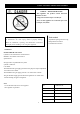
TOOLS AND PARTS NEEDED FOR ASSEMBLY CARBON MONOXIDE HAZARD This appliance can produce carbon monoxide which has no odor. Using it in an enclosed space can kill you. Never use this appliance in a enclosed space such as a camper, tent, home. WARNING: Improper installation, adjustment, alteration, services or maintenance can cause injury, death or property damage. Read the installation, operating and maintenance instructions thoroughly before installing or servicing this equipment.
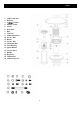
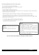
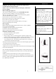
PARTS 1. 3xM6 Castle Nut 2. Reflector 3. 3x¢6mm Washer 4. Emitter Screen 5. Guard 6. Door Plate 7. Base 8. Cast Iron 9. 4xM6x15mm Bolt 10. 4x3/16’’ Bolt 11. Burner 12. 4x3/16’’ Bolt 13. M5x10mm Bolt 14. Tank Housing 15. Igniter Button 16. Control Knob 17. Handle 18. Regulator 19. 3x60mm Pin 20.
NOTE:PLS READ THE FOLOWING SAFETY RULES WARNING: This appliance must only be used outdoors. Using this product in an enclosed area may cause injury, death, or property damage Read the instructions before use. This appliance must be installed in accordance with such regulations as are in force. Do not use the heater in an explosive atmosphere. Keep the heater away from areas where gasoline or other flammable liquids or vapors are stored.
NOTE:PLEASE READ THE FOLLOWING SAFETY RULES. The valve outlet must be maintained in good condition. All gas connections should be checked for leaks utilizing a soap solution. Never use a flame for the purpose. A leak test should be performed with soapy water Whenever connecing a new cylinder. Never use a match to test for leaks. If disassembly is required, a leak test should be performed with soapy water upon reassembly. The heater is designed to operate with a standard 1 Lbs.
WARNING: Proper assembly is the responsibility of the installer, Place heater in a well-ventilated space and do not place in a building, garage or any other enclosed area. An appliance must installed with shelter no more inclusive than: 1.With walls on all sides, but with no overhead cover. 2.Within a partial enclosure which includes an overhead cover and no more than two side walls. These side walls may be parallel, as in a breezeway, or at right angles to each other. 3.
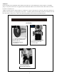
STEP 5 STEP 4 4-1. Fix 3 pcs Pins of 60mm length to the Emitter Screen with 3 pcs Flange Nuts then tighten them. 5-1. Put the Emitter Screen on the Burner. 5-2. Use 4 pcs 3/16” Bolts to connect the Emitter Screen to the Burner. Tighten the Bolts. STEP 6 STEP 7 6-1. Put the Guard on the Burner through the Emitter Screen. 6-2. Put the ends of the Guard into the holes of the Burner. 7-1. Put 3 pcs Washers on each Pins of the 60mm length.
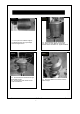
STEP 8 STEP 9 9-1 . Fasten the Reflector with 3 pcs M6 Castle Nuts. 8-1. Put the Reflector through the Pins and on the Washers. STEP 10 STEP 11 10-1. Turn off the Control Knob of the Burner. 10-2. Fix the 1.02 lbs. Gas Tank (not included) to the Regulator (rotate the Gas Tank clockwise toward the Regulator until tighten it). 11-1. Close the Door Plate and lock it with the Handle (rotate the Handle 90 degrees) Warning: The cylinder uses must include a collar to protect the cylinder valve.
OPERATION WARNING: DO NOT attempt to operate heater until you have read and understood all precautions. Failure to do so can result in serious personal injury, death and/or property damage. Before turning gas supply ON Your heater was designed and approved for OUTDOOR USE ONLY . Do Not use it inside a building ,or any other enclosed area. Make sure surrounding areas are free of combustible materials, gasoline And other flammable vapors or liquids. Ensure that there is no obstruction to air ventilation.
OPERATION CAUTION: Avoid inhaling fumes emitted form the heater’s first use. Smoke and odor from the burning of oils used in manufacturing will Appear .Both smoke and odor will dissipate after approximately 30minutes .The heater should NOT produce thick black smoke. Note: The burner may be noisy when initially turned on. To eliminate excessive noise from the burner, turn the control knob to the “LOW” position, then t urn the knob to the level of heat desired.
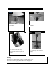
LOCATION HEADER FOR USE BE CAREFUL: WHEN CERTAIN MATERIALS OR ITEMS ARE LEFT ABOVE, BESIDE OR UNDER THIS HEATER WHILE IN USE, THEY WILL BE SUBJECT TO RADIANT HEAT AND COULD BE SERIOUSLY DAMAGED. This heater is primarily used for the heating of outdoor patios, decks, spas, pool and open working areas. Always make sure that adequate fresh air ventilation is provided. Follow the spacing tolerances shown in Figure 1. The minimum clearances, shown in Figure 1, must be maintained at all times.
MAINTENANCE / STORAGE Check your hose assembly: The installation shall only be carried out by competent persons and be in accordance with the relevant codes of practice. Warning: This appliance requires regulator. Check with your gas supplier and or products supplier. Prior to use, check for damaged parts such as regulator, pilot or burner. Never replace or substitute the regulator with any regulator other than the factory suggested replacement.
MAINTENANCE / STORAGE STORAGE: Between uses: Turn the control knob to “OFF” position. Open the door, and disconnect the cylinder. Store heater upright in an area sheltered from direct contact with inclement weather (such as rain, sleet, hail ,snow, dust and debris). If desired, cover heater to protect exterior surfaces and or help prevent debris in air passages. During periods of extended inactivity or when transporting: Turn the control knob to “OFF” position. Disconnect LP cylinder and move to a secure.
TROUBLESHOOTING PROBLEM Pilot will not light Pilot will not stay on Burner will not light PROBABLE CAUSE Gas valve may be OFF SOLUTION Turn the gas valve ON Fuel tank empty Refill LP gas tank Orifice blocked Clean or replace orifice Air in supply system Purge air from lines Loose connection Check all fittings Debris around pilot Clean dirty area Loose connection Tighten connection Thermocouple bad Replace thermocouple Gas leak in line Check connection Lack of fuel pressure Fuel tank i