
Installation Guide


35
Power Unit Column
Adjust the slack in the single point lock cable at the power unit side so that when the
release lever is pulled down both carriage locks will disengage. Tighten the cable
clamps and install the carriage lock covers on each side with the four (4) provided
screws. (Factory tip: Adjust the cables to release the locks just before the lock
release lever has reached maximum travel…this prevents overstretching the cable).
At this time install the carriage lock covers and install the release lever on the power
unit column.
INSTALLING THE LIFT ARM ASSEMBLES
All four (4) arms come completely assembled. The long 2-piece arms are mounted
to the rear of the lift and the shorter 3-piece arms are mounted to the front of the lift.
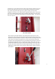
Insert the arm assembles in the correct gaps in the carriage. Align the holes in the
carriage with the holes in the carriage and insert the metal arm pivot pins. Repeat
for all arms. When the arms pivot pins have been installed use the provided metal
retaining rings and attach them to the grooves in the bottom edge of the arm pivot
pins to prevent these pivot pins from moving upward. See photo below for
reference.