
User's Manual


LAUNCH
S3001 User Manual
87
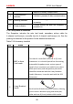
12.2 St
ructure & Accessories
1
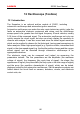
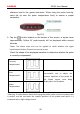
2.2.1 Scopebox structure
F
ig 12-1 Scopebox Structure Diagram
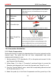
Table 12-1 shows the ports and indicators for the Scopebox.
N
o.
N
ame
D
escription
1 F
ixed signal generator
G
enerate a square signal with fixed 1K
frequency.
2 CH1 Channel 1
3 C
H2 Channel 2
4 C
H3 Channel 3
5 C
H4 Channel 4
6 Ex
ternal trigger
External trigger signal
(*It
only applies if the
Sco
pebox failed to trigger the signal itself.)
7 B-shaped USB Port
Connect to the diagnostic tool via USB
cable so that the signal can be displayed
on the tool.
8 P
ower interface To provide power to it via the power