
User's Manual


LAUNCH
S3001 User Manual
65
Voltage test Testing range DC-400V~+400V
In
put impedance 10Mohm
R
esistance test Testing range 0~40Mohm
F
requency test Testing range 0~25KHz
In
put impedance 1000Gohm
In
put voltage 1~12V
9.2
Structure & Accessories
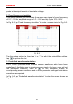
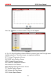
9.2.1 Sensorbox structure
Fig. 9-1 Structural diagram of Sensorbox
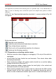
Table 9-1 shows the ports and indicators for S3001 sensorbox
No.
Name Description
1
D
ata receiving LED
Indicator (green) for receiving data from the
diagnostic tool.
2
D
ata sending LED
Indicator (green) for sending data to the
diagnostic tool.