
User's Manual

LAUNCH
S3001 User Manual
93
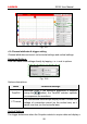
12.3.2 Connection
For different applications, the connection methods may vary.
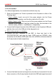
1. Power the Scopebox on: Power is provided to the Scopebox in either of th
e
fo
llowing ways:
• Power adaptor: Insert one end of the power adaptor into the Power
interface of the Scopebox, and the other end to the AC outlet.
• Battery clamps cable: Plug one end of the power adaptor into the Power
in
terface of the Scopebox, and then clamp the other two terminals to the
vehicle's battery (Red to +, and Black to -) respectively.
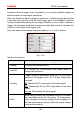
2. Connect the B-shaped terminal of the USB cable to the Scopebox USB port
,
a
nd the other end to the USB port of the diagnostic too
l.
A
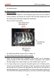
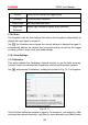
. While testing sensors or actuators,
3
. Connect the BNC connector of the BNC to 4mm test lead to th
e
C
H1/CH2/CH3/CH4, and plug the black (GND) and red (SIGNAL) 4m
m
co
nnectors into the Black (GND) and other color (SIGNAL) banana sockets of
the 6-way breakout leads respectively.
F
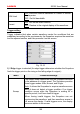
ig. 12-3
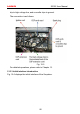
4. Connect the black terminal and signal wire (its other end connected to the red
4mm connector) of the 6-way breakout lead to the GND and signal terminal o
f