LAUNCH X-631/X-631+ Wheel Aligner General Notice Trademark Information Other product names used herein are for identification purposes only and may be trademarks of their respective owners. LAUNCH disclaims any and all rights in those marks. LAUNCH is a registered trademark of LAUNCH TECH. CO., LTD. (short for LAUNCH) in China and other countries.
LAUNCH X-631/X-631+ Wheel Aligner of measurement. z Turn off the power after operation. Check all bolts and parts after maintenance, and tighten the slackened bolts and parts in turn for safety. z Check the packing list before installing. Do not hesitate to contact LAUNCH or LAUNCH distributors for any questions. Precautions z Please read the User’s Manual and the Installation and Parts Manual carefully before operating X-631/X-631+. z Only the qualified technician can operate the Wheel Aligner.
LAUNCH X-631/X-631+ Wheel Aligner inspected as to their operational condition. completely read! • The necessary personal safety equipment for operating, maintenance and repair personnel is available and being worn. Basic safety measures during normal operations: • The operating instructions are always in a legible condition and are completely available at the machine location.
LAUNCH X-631/X-631+ Wheel Aligner electricians! Electrical equipment must be routinely inspected! Re-attach any loose connections! Immediately replace damaged lines/cables! Always keep housings of electrical equipment closed! Access is only permitted for authorized personnel with key/tools! Never spray the housing of electrical equipment with a hose when cleaning! Pay attention to rechargeable battery references and disposal regulations: Lithium Rechargeable batteries: • Do not throw into fire • Only
LAUNCH X-631/X-631+ Wheel Aligner Table of Contents Introduction .................................................................1-1 Definition.................................................................1-1 When Is Wheel Alignment Required.......................1-1 Main Vehicle Alignment Parameter.........................1-1 Toe-in and Toe-out..............................................1-1 Kingpin Inclination (SAI).....................................1-1 Caster...............................
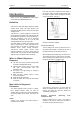
LAUNCH X-631/ X-631+ Wheel Aligner Introduction If the road wheel leans outwards from the vertical, it has positive camber and when leaning inwards from the vertical - negative camber, looking from the front or rear of the vehicle. See Fig.1.1. Introduction Thank you for using X-631/X-631+ wheel aligner manufactured by Launch Tech Co., Ltd.
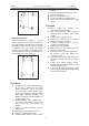
LAUNCH X-631/ X-631+ Wheel Aligner Introduction steering. To increase the tendency of the steering to self-centre, the steering will normally be designed with positive caster. Thrust angle The thrust angle is defined according to the driven mode of vehicle. z Rear wheel driven: the thrust angle equals half of the toe-in difference between the two rear wheels. As shown in Fig.1.5. z Front wheel driven: the thrust angle equals half of the toe-in difference between the two front wheels.
LAUNCH X-631/ X-631+ Wheel Aligner z z z z z Introduction function. The probe rods provide LCD display function. Electronic level function. Black box self-diagnosis function. Front and rear probe rods interchangeable. Special test for Mercedes-Benz and BMW vehicles. Features z z Fig. 1.6 z z Track Width Difference Track width difference is defined as the angle between the joint line of the ground-contact point of left wheels and that of the right wheels.
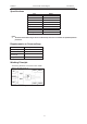
LAUNCH X-631/ X-631+ Wheel Aligner Introduction Specifications Item Front total toe-in Front toe-in Front camber Caster Kingpin inclination Rear total toe-in Rear toe-in Rear camber Thrust angle Range f40嘙 f20嘙 f8.0嘙 f20嘙 f20嘙 f40嘙 f20嘙 f8.0嘙 f5.0嘙 Notes: 1. The above measurement ranges can be confirmed only when the user follows the specified operation procedures.
LAUNCH X-631/X-631+ Wheel Aligner Structures top platform of the cabinet. Mouse and keyboard are on the keyboard drawer. Printer is on the drawer in the middle of the cabinet. The computer host is in the lower compartment of the cabinet. Structures Overall Structure The interface circuit includes the RF main emitter box. The main emitter box is placed in the cabinet.
LAUNCH X-631/X-631+ Wheel Aligner LCD display area has six functions: take the X-631 as an example. [Display start interface]: “Welcome to use X-631” is displayed on LCD as shown in Fig.2.4. Structures [Display for run-out compensation]: To display the current compensation status of the probe rod: 0 indicates the run-out compensation operation should be started for the current probe rod. The interface is as shown in Fig.2.9. Fig.2.
LAUNCH X-631/X-631+ Wheel Aligner [Display Standby status]: “Stand By…” is displayed on LCD. It indicates that the probe rod is in standby mode for saving electricity. The standby mode can be switched to normal working mode as shown in Fig.2.14. Structures Wheel Clamp Hanging Bracket X-631/X-631+ wheel aligner is equipped with 4 wheel clamp hanging brackets as shown in Fig.2.16. Fig.2.14 Button area includes 5 buttons: [Backlight]: Key to switch on/off the backlight of LCD.
LAUNCH X-631/X-631+ Wheel Aligner Brake Pedal Depressor X-631/X-631+ has a brake pedal depressor is as shown in Fig.2.19. It is used to hold the brake pedal down. Fig.2.19 Brake pedal depressor Calibrating Frame and its Converter Connector (Optional) They are mainly used to calibrate the probe rod system of X-631/X-631+ wheel aligner. Fig.2.
LAUNCH X-631/X-631+ Wheel Aligner Basic Operation Procedures Get Vehicle Information Ask the owner for vehicle drivability problems, symptoms, and wheel alignment history, and find out vehicle information such as make, model and year, etc. Check each chassis part carefully, include dust cover, bearing, rock arm, tripod-ball, shock absorber, tie rod ball and steering mechanism, for any loose or wear. Then check to see if the tire pressure, tire treads of the left and right wheels are alike.
LAUNCH X-631/X-631+ Wheel Aligner Operation procedures Operation Instructions Turn on the power switch, start the computer and enter the main interface of the measurement program. The screen displays the main function menu. There are 8 functions available in the main menu: [Standard Measurement], [Quick Measurement], [Additional Measurement], [System Management], [Print], [2D Interface/3D Interface], [Help], and [Exit]. See Fig.4.2 Preparation I. II. III. IV. V.
LAUNCH X-631/X-631+ Wheel Aligner Operation Instructions button to add the standard you can click data provided by the system into this form. If you want to add user-defined data, you need to add it from Standard Data Management interface of System Management. The unit of Wheelbase, Front wheelbase and Rear wheelbase is mm. Special Measurement: For different data of vehicle model, some special measurement methods and operating procedures will occur: 1.
LAUNCH X-631/X-631+ Wheel Aligner Operation Instructions interface as shown in Fig.4.6. Fig.4.8 Fig.4.6 Operating methods: According to the prompts on the picture at the bottom of the interface, measure left, right, front and rear ride height values respectively to see if they are within the standard range or not.
LAUNCH X-631/X-631+ Wheel Aligner z z z Specified rim and tire The brake pedal depressor is installed Counterweight the whole vehicle according to the normal driving conditions. Adjust the seats to the middle positions and fill the gasoline tank full. 2). If the measured values are beyond the tolerance range, it indicates that the vehicle is faulty, and the faults must be eliminated before performing the ride height measurement. 3).
LAUNCH X-631/X-631+ Wheel Aligner for the measurement under this mode; the accuracy of 90°run-out compensation mode is comparatively lower, but each probe rod can finish run-out compensation operation independently under this mode, needless to take other probe rod as reference.
LAUNCH X-631/X-631+ Wheel Aligner FR wheels, and input them into the corresponding data boxes respectively, and then click [Return]. The interface is as shown in Fig.4.14. Operation Instructions in Fig.4.17. Language format Fig.4.17 Fig.4.14 Caution: 1. Before perform kingpin measurement, please install brake pedal depressor and lock the hand brake first, in order to ensure the vehicle wheels cannot move; remove the steering wheel holder finally. 2.
LAUNCH X-631/X-631+ Wheel Aligner Operation Instructions [Double click]: Double click (with left key of the mouse) on the data display forms for camber and toe-in of RL and RR wheels, the corresponding displayed data will be enlarged. The interface is as shown in Fig.4.19. Fig.4.21 Note: The system provides the dynamic measurement and display for these special values, but the measurement result will not be saved in the database.
LAUNCH X-631/X-631+ Wheel Aligner Operation Instructions on the data display forms for camber and toe-in of LR and RR wheels, the corresponding displayed data will be enlarged. [Additional measurement]: This interface provides an operating platform for special measurement, which can measure and display left lateral offset, right lateral offset, axle offset, front setback, rear setback, track width difference and wheelbase difference, etc.
LAUNCH X-631/X-631+ Wheel Aligner 5. Operation Instructions Put down the vehicle to position B1. Adjust the vehicle front toe-in to the allowed scope according to the standard specifications. The interface is as shown in Fig.4.29: Fig.4.26 Operating Methods: 1. Click [Toe-in Curve Change] on the interface of [Front Axle Measurement] to enter Toe-in Curve Change interface as shown in Fig.4.24. 2.
LAUNCH Client information X-631/X-631+ Wheel Aligner Operation Instructions [System management] – [Report setting] for the format setting of the report form). Vehicle license plate number Caution: The report form print function provided by this interface only aims at the individual information report form for the test at this time; the report form print function provided by the main interface aims at all the information report forms saved and done before.
LAUNCH 1. 2. 3. X-631/X-631+ Wheel Aligner This interface provides only the functions of the test and adjustment for front and rear toe-in and camber. For other functions, please select them on the interface of [Standard Measurement]. The default unit for toe-in on this interface is centigrade. Only the vehicle model data is selected, can the display unit for toe-in be in accordance with the toe-in unit set on the interface of System Management]-[System Setting].
LAUNCH X-631/X-631+ Wheel Aligner Operation Instructions this state the system only provides view function. [Delete]: Delete the items selected in client information data form. When performing Delete operation, please note that Delete operation will delete all the corresponding information (including previous testing information) of client. Ensure that you do want to delete the information before performing Delete operation. button to perform information editing Click operation.
LAUNCH X-631/X-631+ Wheel Aligner Operation Instructions and display effect of software system. The interface is as shown in Fig.4.43. Fig.4.41 [Modify]: This function is only applied to modifying the user-defined information in the list. It cannot modify the information imported from the standard data. Fig.4.43 [Basic setting]: With this function the system can be switched between Normal Version and Demo Version, and between Special Version and Common Version.
LAUNCH X-631/X-631+ Wheel Aligner Operation Instructions The interface is as shown in Fig.4.46 [Unit setting]: Used to set the displayed unit system of system data, two types of unit systems can be selected: percentage degree system and degree/minute system. [Unit setting for toe-in]: Aiming to the particularity of the unit for toe-in, the system adds the units of mm and inch.
LAUNCH X-631/X-631+ Wheel Aligner Operation Instructions to enter the interface of the probe status. icon Status of probe rod is used to display the communication status between probe rod and system. The interface is as shown in Fig.4.49. Fig.4.47 Detailed Information of Probe Rod: In the [Probe rod maintenance] interface, click the to enter the interface for the detailed icon information of probe rod.
LAUNCH X-631/X-631+ Wheel Aligner Operation Instructions According to the prompts on the screen, install 4 probe rods on the wheels respectively, and then adjust them level. Click [NEXT] after finished. Fig.4.54 Remove FR probe rod, install LR probe rod on FL wheel, and then adjust the probe rod level. Click [NEXT] after finished. Fig.4.51 The screen will prompt whether the toe-in measurement accuracy of 4 probe rods is normal or not. If not, it is required to recalibrate. Fig.4.
LAUNCH X-631/X-631+ Wheel Aligner click the icon of [Probe Rod Update], the screen will pop up a password inputting box as shown in Fig.4.57. Operation Instructions electronic level and mechanical level due to long-time use of the probe rod. The interface is as shown in Fig.4.59. Fig.4.57 Enter the password (provided by Launch), and then click [OK] button to enter the interface of Probe Rod Update as shown in Fig.4.58. Fig.4.
LAUNCH X-631/X-631+ Wheel Aligner Operation Instructions Fig.4.61 Fig.4.64 According to the prompts on the screen, adjust the calibration bracket level, and then click [NEXT] button. The interface is as shown in Fig.4.62. According to the prompts on the screen, switch on the power supplies of FL and RL probe rods, and switch off the power supplies of FR and RR probe rods, and then click [NEXT] button. The interface is as shown in Fig.4.65. Fig.4.62 Fig.4.
LAUNCH X-631/X-631+ Wheel Aligner Operation Instructions Fig.4.67 4.70 According to the prompts on the screen, please click [NEXT] button to sample data. The interface is as shown in Fig.4.68. According to the prompts on the screen, install 4 probe rods and adjust them level, switch on all power supplies of probe rods, and then click [NEXT] button. The interface is as shown in Fig.4.71. Fig.4.68 Fig.4.
LAUNCH X-631/X-631+ Wheel Aligner Operation Instructions Fig.4.73 Fig.4.76 According to the prompts on the screen, please click [NEXT] button to sample data. The interface is as shown in Fig.4.74. According to the prompts on the screen, turn the calibration frame shaft by 180 degrees, install FL and FR probe rods and adjust them level; switch on the power supplies of the probe rods, and then click [NEXT]. The interface is as shown in Fig.4.77. Fig.4.74 Fig.4.
LAUNCH X-631/X-631+ Wheel Aligner Operation Instructions Fig.4.79 Fig.4.82 According to the prompts on the screen, please click [NEXT] button to sample data. The interface is as shown in Fig.4.80. Click [OK] button to display the calibration value changes. The interface is as shown in Fig.4.83. Fig.4.80 Fig.4.
LAUNCH X-631/X-631+ Wheel Aligner the sensor replacement operation has been performed ever. Data backup and restore The function is used in system data backup application, so as to prevent the WINDOWS system from abnormity caused by external factors (such as virus), and help you to avoid unnecessary loss. The backup function we provide is mainly used to backup the contents of three parts: user and business data information, system configuration file and probe calibration information.
LAUNCH X-631/X-631+ Wheel Aligner Operation Instructions [Client list]: To list the all clients who have been serviced by the alignment test. [Record list]: This list can display the alignment test records (for one time or many times) of the client selected from [Client list]. [Print]: To print the alignment data of the vehicle under test with form or figure format (Please refer to [System Management] – [Report Setting] for the format setting of report form). 3D Interface / 2D Interface Fig.4.
LAUNCH X-631/X-631+ Wheel Aligner Four-probe rode normal light mode (Normal light-4); 2. Four-probe rod high light mode (High light-4); 3. Two-probe rod normal light mode (Normal light-2); 4. Two-probe rod high light mode (High light-2). These four kinds of mode are same with that on the computer. The start-up interfaces of the probe rods are different: Operation Instructions 1. Fig.4.
LAUNCH 6. 7. 8. 9. X-631/X-631+ Wheel Aligner When the data of camber and toe-in is valid, the corresponding data will be displayed; when invalid, “-----” will be displayed. When the system uses two-probe rod working mode, toe-in is of total toe-in, indicated by “TT”; when the system uses four-probe rod working mode, toe-in is of individual toe-in, indicated by “T”. When X-631+ wheel aligner uses No PC Mode, the displayed data units of camber and toe-in are all in Degree/Minute mode.
LAUNCH X-631/X-631+ Wheel Aligner z Maintenance To prolong the life of the equipment, users should maintain it with care. The Wheel Aligner is precision equipment. Here we will tell you the general knowledge about equipment maintenance. z Computer z z z z z z z z z z z z z affect its normal operation. Ensure that the clamp have been firmly secured before installing the probe rod and connecting the power connector. After finishing test, disconnect the power first.
LAUNCH return freight. Send the unit pre-paid to: Warranty THIS WARRANTY IS EXPRESSLY LIMITED TO PERSONS WHO PURCHASE LAUNCH PRODUCTS FOR PURPOSES OF RESALE OR USE IN THE ORDINARY COURSE OF THE BUYER’S BUSINESS. LAUNCH electronic product is warranted against defects in materials and workmanship for one year (12 months) from date of delivery to the user.
)&& 67$7(0(17 7KLV GHYLFH FRPSOLHV ZLWK 3DUW RI WKH )&& 5XOHV 2SHUDWLRQ LV VXEMHFW WR WKH IROORZLQJ WZR FRQGLWLRQV 7KLV GHYLFH PD\ QRW FDXVH KDUPIXO LQWHUIHUHQFH 7KLV GHYLFH PXVW DFFHSW DQ\ LQWHUIHUHQFH UHFHLYHG LQFOXGLQJ LQWHUIHUHQFH WKDW PD\ FDXVH XQGHVLUHG RSHUDWLRQ &KDQJHV RU PRGLILFDWLRQV QRW H[SUHVVO\ DSSURYHG E\ WKH SDUW\ UHVSRQVLEOH IRU FRPSOLDQFH FRXOG YRLG WKH XVHU V DXWKRULW\ WR RSHUDWH WKH HTXLSPHQW 127( 7KLV HTXLSPHQW KDV EHHQ WHVWHG DQG IRXQG WR FRPSO\ ZLWK WKH