
User's Manual

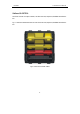

LAUNCH X-431Tool User’s Manual
5
5
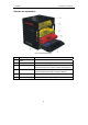
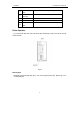
Ports and Indicators
See Fig 2-3 for X-431TOOL connection ports and indicators.
Fig 2-3 ports and indicators
1 Power switch button of main unit 2 Power input of main unit (12V DC)
3 Parallel communication port of main unit 4 Hotkey button
5 Bluetooth indicator of main unit 6 Bluetooth indicator of DIAGBOX
7 CF card ejection key 8 CF card slot
9 Paper Out 10 Diagnostic interface of DIAGBOX
11 Data interface of DIAGBOX
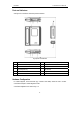
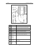
Hardware Configuration
For vehicle diagnosis, some accessories (e.g. connectors and cables) should be used to connect
X-431TOOL main part to vehicle diagnostic socket.
X-431TOOLconfiguration is as shown in Fig. 2-4