
User's Manual

LAUNCH X-431Tool User’s Manual
59
59
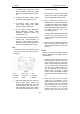
damper.
Besides the two types listed above, there are
other types, such as relay, electronic switch,
etc.
Self-diagnosis of Electronic
Control System
All modern cars are controlled by an Electronic
Control Unit (ECU). The main purpose of the
electronic control system is to provide
maximum engine performance with the least
amount of air pollution and the best fuel
efficiency possible. However, the complexity of
the system may increase the difficulty for its
troubleshooting. The function of self-diagnosis
is for solving such problem with electronic
control system.
Working Principle of Self-diagnosis
The composition of self-diagnosis system is
similar to electronic control system. The basic
component is electronic control unit. The main
purpose of self-diagnosis system is to diagnose
the sensors, actuators, circuits and ECU in
vehicle.
The computer assigns a numeric code for each
specific problem that it detects, and stores
these codes in its memory for later retrieval,
and turns on the fault indicator on the dash
panel to warn the driver. The problem detected
may be: inputted/outputted signal exceeds the
specified range, or some circuit is
short-circuited or open.
Now let’s take gasoline injection control system
as an example to describe the working principle
of the self-diagnosis system. When problem
occurs, the process of diagnosis and treatment
will be as follows:
1) For sensor
If the output signal from the sensor is out of the
specified range of voltage when engine is
running, it will be deemed as fault. For example,
the normal output voltage from coolant
temperature sensor should be in the range of
0.3-0.4V. If not, the situation will be deemed as
fault and fault code will be stored in memory.
Self-diagnosis system can detect damaged
sensor, or short/open circuit, but it can not
appraise the performance of sensor. Occasional
occurrence of abnormal signal will not be
deemed as fault immediately. For not being
interrupted by the sensor fault, the engine will
be controlled by the pre-stored normal coolant
temperature (e.g. 80℃) from the self-diagnosis
system.
2) For actuator
When the engine is running, ECU sends
commands to actuators according to the
practical situation. If the actuator can not work
normally, the monitoring circuit will transmit the
message to the ECU. ECU can make the
message displayed and take measures to
ensure the safe running of engine. For example,
when the power tube in engine ignition system
is out of order, the ignition monitoring circuit
sends feedback to the ECU. ECU emits
warning signal and sends commands to
actuator for stopping injection so as to prevent
the unburnt mixture from damaging the catalytic
converter of exhaust system.
3) For ECU
There is no monitoring circuit, but a monitoring
clock in the ECU for resetting ECU regularly. If
ECU is out of order, its program will not be run
and the clock will not reset the ECU so that
overflow may occur. This situation is deemed as
fault for displaying.
For preventing unexpected stopping of vehicle
caused by problem with ECU, there is a backup
circuit in ECU. When the backup circuit
receives the signal of abnormality from the
monitoring circuit, a spare control program will
be started for keeping the engine running as
pre-programmed.
Readout of Fault Code in Automotive
Self-diagnosis System
The fault in vehicle electronic system is stored
in KAM of ECU as fault code. The fault code
can be read out by the on board diagnostic