V1.00.
LAUNCH X-431Tool User’s Manual Neither LAUNCH nor its affiliates shall be liable to the purchaser of this unit or third parties for damages, losses, costs, or expenses incurred by purchaser or third parties as a result of: accident, misuse, or abuse of this unit, or unauthorized modifications, repairs, or alterations to this unit, or failure to strictly comply with LAUNCH operating and maintenance instructions. Trademark Information LAUNCH is a registered trademark of LAUNCH TECH. CO., LTD.
LAUNCH X-431Tool User’s Manual Table of Contents System information........................................36 User Information .......................................36 About .......................................................36 Introduction .......................................................2 Tool..............................................................36 Features .........................................................2 PIM..............................................................
LAUNCH X-431Tool User’s Manual BLACK (-) battery clip to the negative. Safety Precautions Precautions on Operation z z z z z z z z Precautions on Operating Vehicle ECU Do not collide when operation. For screen, flicker occurs at just the moment of the engine ignition. Be careful when connect the main cable and the diagnostic socket. Tighten the screw and avoid disconnecting or destroying the interface. Handle with care. Avoid collision. Unplug the power after operation.
LAUNCH X-431Tool User’s Manual Introduction z X-431TOOL is a new generation of automobile diagnostic computer. It features wireless communication and color screen. It is based on the technology of open diagnostic platform, the most advanced automobile diagnostic technology brought forward by LAUNCH. The open diagnostic platform represents the highest level of automobile diagnostic technology, and is the developing trend of this field in the future.
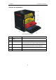
LAUNCH X-431Tool User’s Manual Outline of X-431TOOL X-431TOOL consists of five parts: cabinet, X-431TOOL main unit, adaptor box, DIAGBOX and reference box. Fig. 2-1 shows the cabinet where there are X-431TOOL main unit, adaptor box, DIAGBOX and reference box.
LAUNCH X-431Tool User’s Manual Structure and explanations Fig.2-2 X-431TOOL structure NO. Name Note ① Cabinet ② Adaptor box Used to place adaptors. (Big yellow box) ③ Reference box Used to place CF card, reader/writer, printing paper, USB cable, password envelope, user’s manual and disks. (Small yellow box) ④ DIAGBOX Used to place X-431TOOL DIAGBOX, general adaptors, diagnostic cable and power cable of main unit. (Red box) ⑤ X-431TOOLmain unit Consists of main unit and main unit housing.
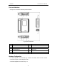
LAUNCH X-431Tool User’s Manual Ports and Indicators See Fig 2-3 for X-431TOOL connection ports and indicators.
LAUNCH X-431Tool User’s Manual Fig 2-4 No. Name Description 1 X-431TOOL Main Unit The screen of main unit can display the operation buttons, the test result and the help information. 2 DIAGBOX Perform vehicle diagnosis 3 CF card Store diagnostic software and data 4 USB cable Connect CF card reader and computer 5 CF card reader Read or write data from/to the CF card 6 Diagnostic connector Dozens of connectors are provided/available for various vehicles. Here shows a typical one.
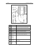
LAUNCH X-431Tool User’s Manual 10 Cigarette cable lighter Get power from the vehicle cigarette lighter 11 Battery w/two clips cable Get power from the vehicle battery 12 Power adapter Convert 100-240V AC power into 12V DC power. 13 Main cable Connect the diagnostic connector and DIAGBOX 14 X-431TOOL cable box Connect DIAGBOX and main unit for wire diagnosis. Printer Operation Fig.
LAUNCH a X-431Tool User’s Manual b c d Fig 2-6 Method I: 1. Turn off the power of main unit. 2. Open the housing of main unit and get out main unit. 3. Open the paper lid on the back of the printer. See Fig 2-6a. 4. Take out the spindle and mount the paper scroll onto the spindle. Put the paper spindle into the printer with correct direction. The paper may not be fed if the direction is wrong. See Fig 2-6b. 5. Lead the paper into slot. See Fig 2-56c.
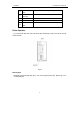
LAUNCH z z X-431Tool User’s Manual Operation temperature: -20℃~70℃ Battery capacitance: 2000mAH First Use of X-431TOOL Start-up Connect the power of main unit and click [ ]. If you want to calibrate the touch screen, please click [hotkey]. If you don’t want to, please wait to enter the start-up menu as Fig 2-7 shows. Press [hotkey] more than 2 seconds, the main unit will be turned off. Current time Active task Overturn Soft keyboard Fig 2-8 [ ]:The use of the icon is similar in the windows.
LAUNCH X-431Tool User’s Manual Input In writing board mode (refer to Fig.2-10), there are eight function keys at the lower left of the soft keyboard. The four ones on the bottom implement the function: to move the cursor leftward, rightward, upward or downward. The other four functions are (from left to right): to delete the first character before the current cursor, clear the hand-writing section, space and return.
LAUNCH X-431Tool User’s Manual Control of App Scrolling Bar Check Box Scrolling Bar is usually at the right side of the touch screen. You can click or drag it to operate. If the content can’t be displayed completely in one page, moving the Scrolling Bar can turn to next page. (Refer to Fig2-13) Common Button [ ] Button at top right corner of the interface: After clicking it, current interface will be closed. When editing is being done, clicking of the button will be treated as quitting the editing.
LAUNCH X-431Tool User’s Manual z Vehicle Diagnosis z Conditions for Test z z Turn on the key. z The voltage of vehicle battery should be 11-14V. The rated voltage of the X-431TOOL is 12V. z The throttle should be in the closed position. z X-431TOOL works in the temperature range of 0-50 ℃ . (30 minutes of warming-up may be necessary when the ambient temperature is 5℃) . Insert one end of X-431TOOL diagnostic cable to diagnostic interface of DIAGBOX.
LAUNCH X-431Tool User’s Manual unit is insufficient, the above methods can also be used to get power. (There is an input power port for the main unit. Please refer to Fig. 2-2). Operation More and more vehicle, models and systems can be tested by X-431TOOL. Please log on the http://www.X431.com and update the latest software in time. Entering Function Menu After connection, press [POWER] key to start X-431TOOL.
LAUNCH X-431Tool User’s Manual model as an example to describe. Button descriptions: ♦ [Ok]: to continue the diagnosis. ♦ [BACK]: to return to the previous interface. Control module Click [OK] button, the screen will display the information as shown in Fig 3-6 Note: The test operation for different systems is similar. Here we only take Volkswagen model as an example to describe. Fig 3-4 Button descriptions: ♦ [BACK]: to return to the previous interface. ♦ [HELP]: to display the help information.
LAUNCH X-431Tool User’s Manual Fig 3-7 Fig 3-8 There are several pages for the menu. Click [PAGE DOWN] to see the next page. Note: The information is from the vehicle ECU. If you have any question during test, don’t hesitate to contact LAUNCH to get answer as soon as possible. Note: The test operation for different systems is similar. Here we take [Engine electronics] as an example for demonstration. Button descriptions: ♦ [OK]: to go on the test. ♦ [PRINT]: to print the information.
LAUNCH 7. 8. 9. 10. 11. X-431Tool User’s Manual Read individual measuring value Diagnose final control Code control unit Login procedure End output Read ECU Information Click [Read ECU Memory] on the function menu. The screen will display the information on ECU of the tested system. See Fig 3-12. Fig 3-10 Fig 3-12 Button descriptions: ♦ [HOME]: to return to the homepage of vehicle diagnosis. ♦ [BACK]: to return to the previous interface. ♦ [HELP]: to display the help information.
LAUNCH X-431Tool User’s Manual Fig 3-13 Fig 3-15 Button descriptions: ♦ [HOME]: to return to the homepage of vehicle diagnosis. ♦ [BACK]: to return to the previous interface. ♦ [PRINT]: to print the test result. Click [OK] button to return to the function menu. Read Measuring Value Read Measuring Value of Volkswagen Click [PRINT] to print out the test result. Fig 3-14 shows an example of printed report. On the function menu, click [read measuring value] to read the datastream. See Fig 3-16.
LAUNCH X-431Tool User’s Manual memory function. ♦ [CANCEL]: to return to the function menu. ♦ [BACK SPACE]: to delete the wrong number. For example, when “1” is inputted for the channel No., the screen will display the live value of data stream of the channel. See Fig 3-17 Fig 3-18 Click [GRAPHIC-2] to display the waveforms of 2 data stream items. See Fig. 3-19. It is convenient for the user to make live comparison between two correlative data stream items.
LAUNCH X-431Tool User’s Manual Read Measuring Value of other series On the function menu, select [read measuring value] to enter the [choose measuring option] menu. Click the measuring option to view. (See Fig. 3-20) Fig 3-21 Click [OK]; the screen will display the dynamic data of selected datastream. (See Fig 3-22). Fig 3-20 Button descriptions: ♦ [PAGE DOWN]: to display the next page. ♦ [HOME]: to return to the homepage of vehicle diagnosis. ♦ [BACK]: to return to the previous interface.
LAUNCH X-431Tool User’s Manual ♦ [PRINT]: to print the test result. Erase Fault Memory Click [Erase Fault Memory] on the function menu. X-431TOOL starts to erase the fault code. (See Fig 3-23). Basic Setting Basic setting is necessary for some systems after service is done. Click [Basic Setting] on the function menu. Click the number button to input the group No. (See Fig 3-25) Fig 3-23 Button descriptions: ♦ [YES]: to execute read and erase the fault code. ♦ [NO]: to return the function menu.
LAUNCH X-431Tool User’s Manual Fig 3-26 Fig 3-28 Note: Refer to appendix Ⅳ for the basic setting channel of Volkswagen. Click [OK]. If the adaptation is successful, the screen will be displayed as shown in Fig 3-29 Button descriptions: ♦ [OK]: to make sure the inputted channel. ♦ [CANCEL]: to return the function menu. ♦ [BACK SPACE]: to delete the wrong input number After the correct channel No. is inputted, click [OK] button. X-431TOOL prompts user to input the matched data.
LAUNCH X-431Tool User’s Manual The screen will display the information as shown in Fig 3-32 Fig 3-30 Button descriptions: ♦ [OK]: to make sure the inputted channel. ♦ [CANCEL]: to return the function menu. ♦ [BACK SPACE]: to delete the wrong input number Fig 3-32 Button descriptions: ♦ [YES]: to perform the test for next component. ♦ [NO]: to quit the test and return to the function menu. For example, when “1” is inputted for the channel No., the screen will display the live value of the channel.
LAUNCH X-431Tool User’s Manual Click [OK] to enter the interface about the ECU as shown in Fig 3-36. Control Unit Code Click [Control Unit Code], the screen will display the information as shown in Fig 3-34. X-431TOOL prompts user to input the code control unit. Click the number button to input the group No. Fig 3-36 Note: The information is from the vehicle ECU. If you have any question during test, don’t hesitate to contact LAUNCH to get answer as soon as possible.
LAUNCH X-431Tool User’s Manual Click [OK] to return to the function menu. Login Procedure Click [Login Procedure] on the function menu. The screen will be displayed as shown in Fig 3-38 X-431TOOL prompts user to input the password. Click the number to input the password. Fig 3-39 Click [OK] button to return to the function menu. Resetting Maintain/oil Indicator On the diagnosis menu (see Fig 3-40& Fig 3-41), click [Resetting maintain/oil indicator] to execute this function.
LAUNCH X-431Tool User’s Manual Fig 3-41 Fig 3-42 The following is the resetting options of the maintain indicator. Maintain option Resetting indicator 12068km/6 m OIL 24139km/12 m OIL 、IN1 36209km/18 m OIL 48278km/24 m OIL、IN1、IN2 60348km/30 m OIL 72417km/36 m OIL、IN01 84487km/42 m OIL 96556km/48 m OIL、IN01、IN2 OBDⅡ Diagnostic function Freeze Frame Data Freeze frame test of OBDⅡis used for the OBD Ⅱ vehicle.
LAUNCH X-431Tool User’s Manual Fig 3-44 Click [OK] to view the freeze frame data. (See Fig 3-45). Fig 3-46 Fig 3-45 Fig 3-47 Readiness Test Diagnostic Socket Description On the [select diag function] menu, choose [readiness tests] to enter the test. The screen will display the select vehicle. Click the tested option then click [ok] to check the test result. Click [back] to return the function menu. (See Fig 3-46 and Fig 3-47). X-431Infinte provides diagnostic socket description.
LAUNCH X-431Tool User’s Manual Fig 3-48 Fig 3-50 If there is still the glittery pane, you can continue to click it till the diagnostic socket location is displayed. (See Fig 3-49). Update of diagnostic software User Registration Log on www.X431.com. Select the favorite language on the pull-down menu at the lower right of the interface to enter the homepage. See Fig 3-51.
LAUNCH X-431Tool User’s Manual onto the member area, and then click “product control” to register the newly purchased product. Refer to the section “Member login”. The terms of service is shown in the screen. After reading and fully understand it, click “I accept” button to enter the interface shown in Fig 3-52. z Fig 3-54 z Fill User Information Fill in Product Information Fill in the serial No. of DIAGBOX, registration No. and dealer code in the interface shown in Fig 3-53.
LAUNCH X-431Tool User’s Manual steps. Note: when choose the user type, the common users may choose the customer. If the dealer and the branch want to log to the website, please use the user information given by LAUNCH head office. Note: 1. After log successfully, the screen will display the interface as shown in Fig 3-57(default download center interface). 2. Fig 3-57 [Download Center]: Refer to “software download”. [Purchase Center]& [Update center]: Refer to “software purchase and update”.
LAUNCH X-431Tool User’s Manual Click [save] to put into the[X-431TOOL update]. Display Program Download When download the diagnostic program, users can also download the display program. On the drop-down menu, users select the language then click [down]. On the pop-up menu, click [save] to put the program into the[X-431TOOL update]. Fig. 3-59 1-CF card reader 2-USB cable 3-USB Port 4-Computer 5-CF card z Insert the CF card into the CF card reader.
LAUNCH X-431Tool User’s Manual Precaution on Operation of the CF Card Reader: 1. Do not unplug the CF card reader from the USB port while its LED is blinking, otherwise data would be damaged! 2. Pull out the CF card The CF card must not be pulled out when the CF card reader is being used. Otherwise, the data in the CF card will be lost. Fig 3-60 Procedure for pulling out the CF card: On the desktop of Windows, open the window of “My computer”.
LAUNCH X-431Tool User’s Manual Fig 3-65 Fig 3-63 Click [pay] to buy the software. The bought software will be automatically added in the user’s download center. Click [clear] to clear all the software in the shopping cart. Click [purchase other] to buy other software. (See Fig 3-66). Select the module for update in the interface shown in Fig 3-63, and click “Update” icon to update. When the update is complete, prompts will appear to notify successful update.
LAUNCH X-431Tool User’s Manual Flow Chart of X-431TOOL Update for New User Log on www. X431. com Select language For member For unregistered user Enter username and PW Click [Register] Read terms of service, click [I accept] Complete the registration Click [Login] Select DAIGInfinite Serial No.
LAUNCH X-431Tool User’s Manual PDA function In the X-431TOOL operation interface, click [start] to pop up the menu that included the main PDA functions executed by equipped stylus.(See Fig 4-1) The items and their respective functions in the menu are shown in the following table. Fig 4-1 PDA Function Summary System Information PIM (Personal Information Management) Tools User Information Set the user name, company and telephone number etc. information by user.
LAUNCH Control Panel X-431Tool User’s Manual World Time The time of many big cities in the world are offered. It is a helpful assistant for your travel. Mini Dictionary An English-Chinese dictionary embodies a large number of words, which cover all fields to overcome your inconvenience in language. Picture View To enjoy all kinds of pictures which can be zoomed in/out. Application To link the application with the ‘Start’ menu, or delete it from the ‘Start’ menu.
LAUNCH X-431Tool User’s Manual System information User Information The user information is filled out by the user. To register the information, the rights and interests of the user will be more guaranteed.
LAUNCH X-431Tool User’s Manual Fig 4-4 Fig 4-6 1) Click [Start] button. 2) Select ‘Tools’ in the pop-up menu. 3) Select the function needed in the pop-up submenu. Calculator simple and calculator scientific (refer to Fig 4-5 and Fig 4-6): 1) Click numeral keys on the screen to input. 2) Or activate Soft Keyboard, and click numeral key on Soft Keyboard to input. 3) The operation is the same as that for normal calculator.
LAUNCH X-431Tool User’s Manual Dictionary 1) In the pop-up menu of ‘Tools’, select ‘Dictionary’ to open the Dictionary interface. (See Fig 4-9) 2) Activate Soft Keyboard, and input words. 3) Select the word from the list on the left. 4) Click the word, and then you can find the translation in the right list. Fig 4-7 World Time Fig 4-9 Picture View 1) Click [Start] button. 2) Select ‘Tools’ in the pop-up menu. 3) In the pop-up ‘Tools’ list, select ‘Preview’ to open the Picture interface.
LAUNCH X-431Tool User’s Manual Fig 4-11 Fig 4-10 Memo Browse the pictures in current directory icon on 1) In the Picture interface, click the top to browse the previous picture. icon on 2) In the Picture interface, click the top to browse the next picture. Note: This operation is needed only when more than one picture has been stored. The basic functions of Memo include: add new memo, view memo, delete memo, browse by types, etc. 1) In the pop-up ‘PIM’ list, select ‘Memo’ to open the Memo interface.
LAUNCH X-431Tool User’s Manual Fig 4-13 Fig 4-12 Delete Memo 1) In the list box of the Memo interface, click the memo that you want to delete. 2) Then you can delete the memo in the opened Memo Edit interface. 3) Click [Delete] button to delete the memo and close the Memo Edit interface. Add New Memo 1) In the Memo interface, click [New] button to open the New Memo interface. 2) Activate Soft Keyboard, and fill the subject and contents.
LAUNCH X-431Tool User’s Manual Fig 4-14 Fig 4-15 Browse By Types 1) Click the [▼] button on the top right of the Memo interface so that the type list pops up. 2) Select the type in the list. 3) Then you can see the memo belonging to the type in the list box. Add New Address 1) In the Address Book interface, click [New] button to open the Address New interface. (See Fig 4-16) 2) Activate Soft Keyboard, and fill the detailed information on relatives and friends.
LAUNCH 2) 3) X-431Tool User’s Manual Then the detailed information about the person will be shown in the opened Address Edit interface. Click [OK] button to close the Address Edit interface. 2) 3) Activate Soft Keyboard, and input the name you want to search. Click [OK] button, and then you will see that the name you search is highlighted in the list box. Edit Address 1) In the list box of the Address Book interface, click the name that you want to edit.
LAUNCH 3) 4) X-431Tool User’s Manual the Memo interface. Click [Options] button to open the To Do Display interface. (See Fig 4-19) Click [New] button to open the To Do New interface. Add New To Do Fig 4-21 View To Do 1) In the list box of the To Do interface, click the [to do] option that you want to view. 2) Then the contents of the To Do will be shown in the opened To Do Edit interface. 3) Click [OK] button to close the To Do Edit interface.
LAUNCH 2) 3) 4) 5) 6) 7) X-431Tool User’s Manual pops up. In the type list, select ‘Edit Group’ to open the Edit Group interface. See Fig 4-22. In the Edit Group interface, activate Soft Keyboard. In the text box at the bottom of the interface, input the name of the type. Click [New] button to add a new type and it will be displayed in the list box of the Edit Group interface. Select one type in the list box, and then click [Delete] button to delete it.
LAUNCH X-431Tool User’s Manual 7) and close the Select Date interface. You may see the date you set on the button on the top right of the Schedule interface. Fig 4-24 1) 2) 3) 4) 5) In the pop-up list of ‘PIM’, select ‘Schedule’ to open the Schedule interface. Click the Date button on the upper left of the interface to open the Select Date interface. In the list box in the middle of the interface, all schedules on that day corresponding to the Date button will be displayed.
LAUNCH X-431Tool User’s Manual 5) View Schedule 2) In the Schedule interface, select the date that has been scheduled. (Refer to the section “Add New Schedule Æ Set the date of the schedule”) 3) In the list box of the Schedule interface, click Scrolling Bar to turn to next page, and click the schedule you want to view. 4) Then the contents of the schedule will be shown in the opened Schedule View interface. 5) Click [OK] button to close the Schedule View interface.
LAUNCH X-431Tool User’s Manual Application It displays the application information contained in the ‘Start’ menu, including the group name, the submenu, etc. Fig 4-28 System Control Panel Fig 4-30 The control panel includes all interrelated software and hardwareconfigurations. It makes the software more custom-built for you by conFiguring. 1) 2) 3) Click [Start] button. Select ‘Control Panel’ in the pop-up menu. Open the Control Panel interface.
LAUNCH X-431Tool User’s Manual Note: Quit all other applications before saving the modification. Fig 4-31 4) Insert a new submenu: Click [Insert] button and input the item name and the file path. Then choose a group as its parent and click [OK] button. The path can be inputted directly or found out in a dialogue box after clicking [Browser] button. See Fig 4-31 and Fig 4-32. Click [OK] button after selecting an item in the list. Then the selected file will be automatically copied to the edit box.
LAUNCH X-431Tool User’s Manual 5) set ‘Hours’, ‘Minutes’ and ‘Seconds’ directly. Click [OK] button to save and close the Set Time interface. Fig 4-33 Clock User can set the time and the time zone of the system. Fig 4-35 Set Date: 2) In the Date/Time interface, you can set date directly. 3) Click [ ] icon to the left of the month or year to select the previous month or year. 4) Click the [ ] icon to the right of the month or year to select the next month or year.
LAUNCH X-431Tool User’s Manual Language You can make selection among several languages for convenient operation of the system. Fig 4-36 After finishing all settings, click [OK] button in the Date/Time interface to exit and close the interface. Fig 4-38 Contrast It is for adjusting the contrast of the screen to make the interface clearer. 1) 2) 1) In the Control Panel interface, click ‘Contrast’ icon to open the Contrast interface. See Fig 4-37.
LAUNCH 3) X-431Tool User’s Manual accurately, and wait until it changes. Then one step of calibration is finished. After calibration is finished for all corners, the system will automatically return to the start-up main interface. Note: ♦ Do not click the touch screen before the cross cursor appears. ♦ In the calibration step, if you fail to click the cross cursor accurately, the cross cursor will be displayed on the screen again and again until the calibration is finished completely.
LAUNCH X-431Tool User’s Manual Answer: There are two possible causes: 1. The downloaded diagnostic program is not put in the same folder as other diagnostic programs. Please move it to the same folder as others. 2. The diagnostic program is not fully downloaded. Please download the program again. FAQ X-431TOOL is a hi-tech product. With the development of modern automotive industry, more and more new technology will be adopted and there may be questions during operation.
LAUNCH z X-431Tool User’s Manual is connected to vehicle diagnostic socket through cables and connectors.
LAUNCH X-431Tool User’s Manual Answer: The possible cause is that no CF card is in the machine, or CF card is inserted improperly or damaged. If it is damaged, it is necessary to make a new one. Question: How to know what applications (interfaces) are opened. Answer: Click the active taskbar icon, then the pop-up list will display the applications (interfaces) opened.
LAUNCH X-431Tool User’s Manual Question: The screen does not respond or responds wrongly when I click it with stylus. What should I do? Answer: There may be no paper in the printer or the printer is not well connected. Please mount a roll of new paper. See the section “Printer Operation” in the User’s Manual. Answer: It is necessary to calibrate the screen. Please refer to the section “Calibrate Touch Screen” in User’s Manual.
LAUNCH X-431Tool User’s Manual pop-up list will display the applications (interfaces) opened. analysis. Question: Why are there too many trouble codes? Question: Why can’t I do operation in current interface? Answer: It may be caused by poor contact or poor grounding. Make sure that the vehicle model/year is selected correctly and the vehicle is equipped with the system. Answer: There are two possible causes: 1. Your current interface has exited illegally.
LAUNCH X-431Tool User’s Manual About ECU In the last two decades, we have seen more and more extensive application of IT and electronic technologies in modern vehicles. Many vehicle control systems, typically EFI (Electronic Fuel Injection), ABS (Anti-block Braking System), SRS (Air Bag), TC (Traction Control), AT (Automatic Transmission), etc., are computerized. Computerization makes the control precisely, quickly, effectively and safely.
LAUNCH X-431Tool User’s Manual 3) In braking system: vehicle speed, wheel speed, deceleration, sliding rate, braking pedal force, braking pedal position sensors, etc. into electrical parameter. 2) A/D converter: it converts the analogue signal from the sensor into digital signal. Then the digital signal can get into SMC. 4) In steering control system: steering, vehicle acceleration, vehicle speed sensors, etc. 3) SMC: it consists of I/O interface, CPU, RAM/ROM, etc.
LAUNCH X-431Tool User’s Manual damper. 0.3-0.4V. If not, the situation will be deemed as fault and fault code will be stored in memory. Self-diagnosis system can detect damaged sensor, or short/open circuit, but it can not appraise the performance of sensor. Occasional occurrence of abnormal signal will not be deemed as fault immediately. For not being interrupted by the sensor fault, the engine will be controlled by the pre-stored normal coolant temperature (e.g. 80℃) from the self-diagnosis system.
LAUNCH X-431Tool User’s Manual system or external scan tool. sensor into digital signal needed by CPU. The on board diagnostic system in different vehicle may indicate the fault in different way. In general, the following ways are popular: 2. CPU The digital signal is transferred to CPU for computation and logical operation so that correct air/fuel mixture can be obtained. CPU can also compute ignition timing and idle speed, and control exhaust, fuel and diagnostic systems.
LAUNCH X-431Tool User’s Manual connected to ECU because most ECU’s are operated under low voltage (about 5V). Whenever you work in the vicinity of ECU or engine control system, please obey the following precautions: 1. Never damage the lead or connector. Prevent them from being grounded or contacting with an unexpected power source. 2. Never use the electrical test tool that is powered by 6V battery or over. Strong current may cause the element in ECU broken or shorted.
LAUNCH X-431Tool User’s Manual Appendix: X-431 TOOL Connectors and Sockets Location Model Connectors OBDII [SMART OBDⅡ-16E] diagnostic connector OBDⅡ-16 socket is often under instrument panel. The location will be different as different model. HYUNDAI 1. [MITSUBISHI/ HYUNDAI -12+16] diagnostic connector 2. [SMART OBDⅡ-16E] diagnostic connector z HYUNDAI socket is often under the instrument panel by the driver’s side.
LAUNCH MITSUBISHI Renault X-431Tool User’s Manual 1.[MITSUBISHI/HYUNDAI-12+ 16] diagnostic connector 2. [SMART OBDⅡ-16E] diagnostic connector [SMART OBDⅡ-16E] diagnostic connector OPEL [SMART OBDⅡ-16E] diagnostic connector FIAT [FIAT-3] diagnostic connector BMW 1. [BMW-20] diagnostic connector 2. [SMART OBDⅡ-16E] diagnostic connector MERCEDES BENZ 1. [MERCEDES BENZ-38] diagnostic connector 2. [SMART OBDⅡ-16E] diagnostic connector 3.
LAUNCH X-431Tool User’s Manual instrument panel. z Beetle socket, under side instrument panel. 1. [AUDI-4] diagnostic connector 2. [SMART OBDⅡ-16E] diagnostic connector AUDI G.M. FORD CHRYSLER PEUGEOT LANDROVER SUBARU VOLVO GREAT WALL Note: for connecting AUDI4PIN socket, connect black end of diagnostic connector to black socket, white to white. VOLKSWAGEN socket is alive so it doesn’t need external power. 1. [SMART OBDⅡ-16E] diagnostic connector 2. GM/VAZ-12 diagnostic connector 1.
LAUNCH CHERY KINGLONG ZHONGHUA CAR X-431Tool User’s Manual connector 2. [SMART OBDⅡ-16E] diagnostic connector z OBD Ⅱ -16 trapeziform socket is under instrument panel.。 1. [FIAT-3] diagnostic connector 2. [SMART OBDⅡ-16E] diagnostic connector z FIAT-3 socket is in engine compartment.。 z OBD Ⅱ -16 socket is in left bottom of instrument panel in compartment. z CHERY ABS socket is under instrument panel. z Sockets for CHERY , MOTOROLA K2 electronic control system,next to firewall in engine compartment.
LAUNCH Warranty THIS WARRANTY IS EXPRESSLY LIMITED TO PERSONS WHO PURCHASE LAUNCH PRODUCTS FOR PURPOSES OF RESALE OR USE IN THE ORDINARY COURSE OF THE BUYER’S BUSINESS. LAUNCH electronic product is warranted against defects in materials and workmanship for one year (12 months) from date of delivery to the user. This warranty does not cover any part that has been abused, altered, used for a purpose other than for which it was intended, or used in a manner inconsistent with instructions regarding use.
LAUNCH X-431Tool User’s Manual X-431 TOOL Serial No. DEALER CODE Note: 1. ‘X-431 TOOL Serial No.’ label is attached by LAUNCH before shipping. 2. Dealer should fill in the Dealer Code when selling the machine to customer and stamp on the code. 3. The ‘X-431 TOOL Serial No.’ and 'Dealer Code' are useful when updating the software. Refer to the section 'Update of Diagnostic Software'. Keep the user’s manual carefully. 4. Dealer should log on http://www.X431.
LAUNCH X-431Tool User’s Manual Statement: LAUNCH reserves the rights to make any change to product designs and specifications without notice. The actual object may differ a little from the descriptions in the manual in physical appearance, color and configuration.
FCC STATEMENT 1. This device complies with Part 15 of the FCC Rules. Operation is subject to the following two conditions: (1) This device may not cause harmful interference. (2) This device must accept any interference received, including interference that may cause undesired operation. 2. Changes or modifications not expressly approved by the party responsible for compliance could void the user's authority to operate the equipment.