
User's Manual
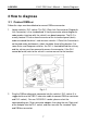
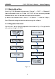
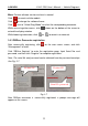
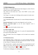
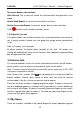
Table Of Contents
- Copyright Information
- Trademark Information
- Precautions on Using X-431 PRO
- Precautions on Operating Vehicle’s ECU
- 1 Introductions
- 1.1 Product Profile
- 1.2 Features
- 1.3 Knowledge of X-431 PRO
- 1.4 Technical Parameters
- 1.5 Package List
- 2 Preparations
- 3 How to diagnose
- 4 Others
- 4.1 Email
- 4.3 Browser
- 4.4 Using Bluetooth
- 4.5 Camera
- 4.6 Gallery
- 4.7 Music
- 4.8 Calendar
- 4.9 Alarms
- 4.10 File Manager
- 4.11 Display
- 4.12 Set screen lock
- 4.13 Applications
- 4.14 Language & input
- 4.15 Set date & time
- 4.16 View and release the memory of SD card and X-431 PRO
- 4.17 Restore X-431 PRO to factory settings
- 4.18 Downloads
- 4.19 Install / Uninstall APPS
- RCU-G user's manual_for certification_.pdf.part.pdf

LAU NCH X-431 PRO User’s Manual — Vehicle Diagnosis
3 How to diagnose
3.1 Connect DBScar
Follow the steps mentioned below to connect DBScar connector:
1. Locate vehicle’s DLC socket. The DLC (Data Link Connector or Diagnostic
Link Connector) is the standardized 16-cavity connector where diagnostic
code readers interface with the vehicle's on-board computer. The DLC is
usually located 12 inches from the center of the instrument panel (dash),
under or around the driver’s side for most vehicles. If Data Link Connector is
not located under dashboard, a label should be there telling location. For
some Asian and European vehicles, the DLC is located behind the ashtray
and the ashtray must be removed to access the connector. If the DLC
cannot be found, refer to the vehicle’s service manual for the location.
Fig. 3-1
2. Plug the DBScar diagnostic connector into the vehicle’s DLC socket (It is
suggested to use the OBD 2 extension cable to connect DBScar connector
and DLC socket.). For non-16PIN DLC socket, please select the
corresponding non-16 pin connector adaptor, then plug the non-16pin end
of the adaptor into the DLC socket, and then connect the standard 16pin
end DBScar connector.
7